Basics of Electricity
Before we begin with creating circuits, there are a few things we need to understand about electricity to make sure that everyone is safe, and to avoid accidentally breaking the hardware that we will be using in this unit.
In short, electricity is the flow of electrons from one place to another. Because electrons have a negative electric charge, this movement causes an imbalance between the negative and positive elements of an electrical system.
We can take advantage of this imbalance and flow of electrons by both containing the electrons within a system, and causing that system to loop back on itself. Because the charges naturally wan to to be balanced with an even distribution of electrical charge, when there are a large amount of electrons in one location of the system, they will travel along the wires from point A to point B. However now the electrons are causing an imbalance in the other location, so they continue along the wires until they reach point A again, at which point the cycle repeats.
This processes creates the electrical energy that we can use to power all of our electrical devices.
Components of Electricity
Electricity is comprised of three main parts
- voltage: the force that forces the electrons to flow within the system; measured in
volts. - current: the amount of electrons that are moving through the system; measures in
amps. - resistance: elements that impede the travel of the electrons through the system; measured in
ohms. Also called theload, the resistance is always measured between two different points in the circuit.
Lets compare these parts to the flow of water.
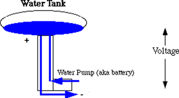
In this image, the electrons would be the water. The voltage would be the pressure created by the water pump. This pressure would cause water to flow up to the main reservoir, and back down into the pump continually. The current would be the volume of water moving through the pipes, and the resistance would be the size of the pipes. Larger pipes would allow for the water to flow through easier.
Lets keep the water analogy, but instead compare the movement to a river.

The voltage would be the flow of the river, this time caused by gravity.
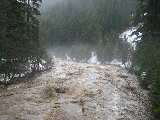
The current, again, is the amount of water flowing through the river and can make the difference between a slowly tricking stream and a powerful storm-surge.

Resistance in the river is brought on through rocks and logs and other elements that disrupt the water flow. A river with no rocks in it will flow smoothly, but a river with many large rocks will turn into rapids.
Much like a river, electricity will only flow in a single direction. In our circuits the power will move from the source, labeled + through the circuit, to the opposite end labeled labeled - or ground. You cannot try to cause the circuit to flow in the opposite direction, but you can block or change the flow of the electricity from positive to ground like you can alter a river’s flow with dams and canals.
Ohm’s Law
As you may have noticed, all three of these elements, voltage, current, and resistance are closely related. In fact we can calculate each of the values for these elements with a simple equation known as Ohm’s Law:
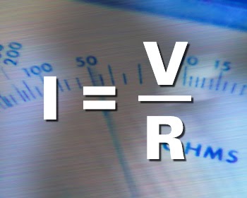
- V = voltage
- I = current
- R = resistance
We can also combine the voltage and current to determine the power of a circuit, measured in watts.
watts = volts X amps
Resistors
When building an electrical circuit, we are connecting points on a battery via wires so that the electrons stored in the battery can travel through the wires, power a device, and then return to the other end of the battery, like the image below. (the green is the wire, and the arrow shows the flow of electrons)

One thing that is not shown is the resistance. Everything naturally has some amount of resistance; the air, water, wires, you all have a resistance of some amount. Electricity will travel along the path of least resistance. In the case of our electrical circuits, the resistance of our wires are essentially negligible, and much lower than the insulation around them so the electricity will flow through the wires when they are connected to the power source. However, many of elements we will use in this unit cannot handle the natural flow of electricity, so we have to incorporate different resistors into the circuit to keep our electronics from exploding when we plug them in. these resistors restrict the flow of electricity by a specific amount.
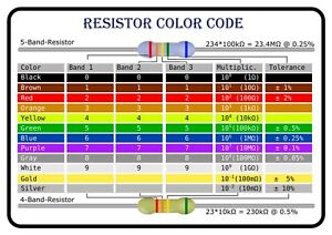
Fixed Resistors
Fixed resistors are elements that we connect into the electrical circuit in order to add a resistance that does not change into the system. These resistors have various sizes and shapes depending on the amount of resistance the offer.
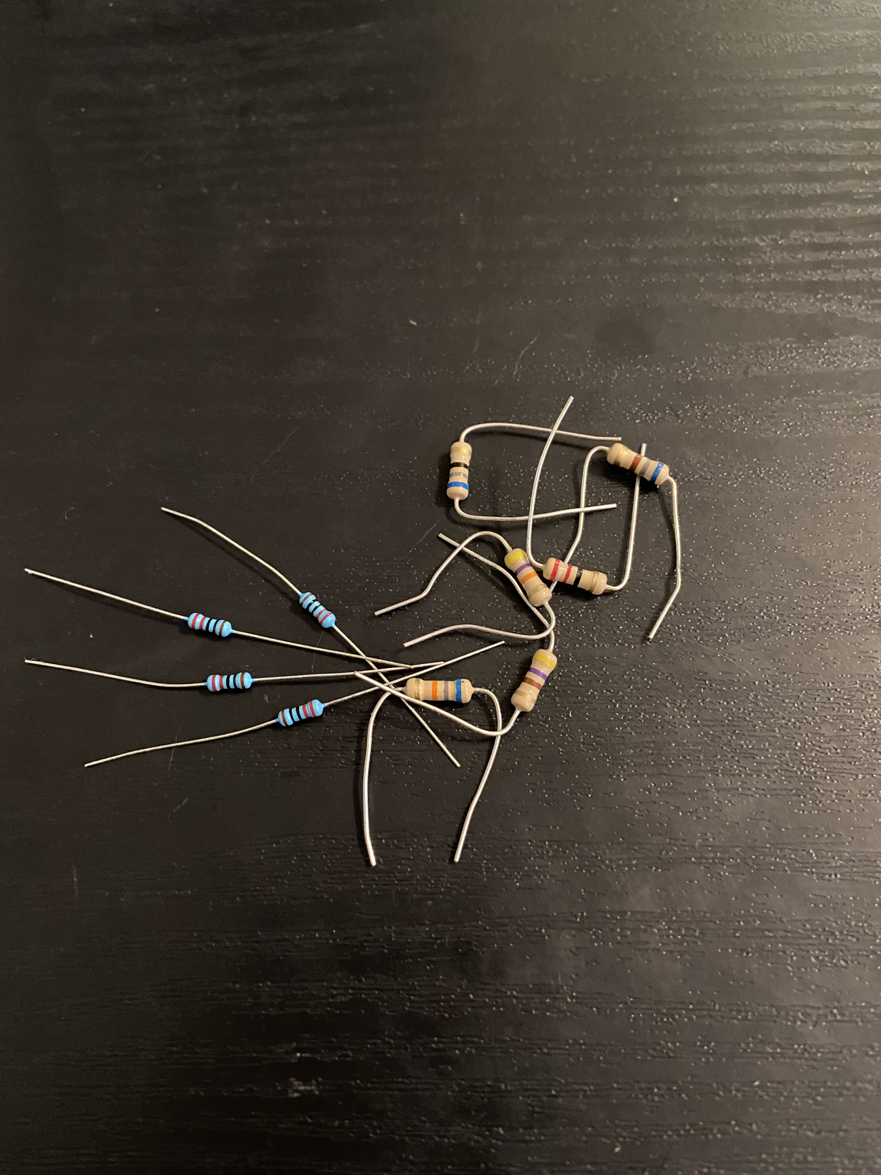
The chart below will show you how to identify the resistors we will use throughout this unit. The value can change depending on the color and order of bands printed on the resistor, as well as the color of the resistor itself.
Variable Resistors
Variable resistors are resistors that can change the amount of resistance they are currently applying to the system. Several variable resistors include potentiometers (dials), soft pots, and several analog sensors. All of which will be discussed in more detail later in the unit.
There are several other components to electricity and building circuits, but this covers the information that you should know about before attempting to build your first circuit. We will dive into these other components over the course of the next three chapters.