Making a Controller - Sending Data to P5
In this lesson we will start to combine elements from our work in P5 with the Arduino codes and circuits that we have been learning in the past two chapters. To start, we will send information from the Arduino to P5 and have P5 respond in real time. This can be a fairly time consuming process until you get the hang of it, so be sure to go through this lesson slowly and make sure you have an understanding of the steps and concepts before you move onto the next section.
The Circuit
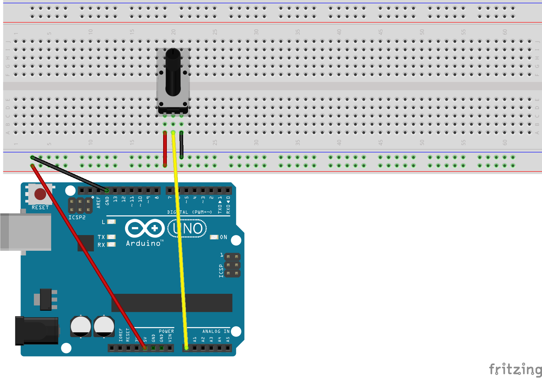
On their own, each element of this process is not complicated. It is making all of the elements talk to each other that we want to focus on. We can begin by creating a simple circuit with a potentiometer like the one shown below:
- Connect pot to power & ground.
- Connect middle pin to A0. (this can be any of the analog pins, but you will have to update the code examples below to match the pin of your choice.)
This will be a basic basic circuit. For now all we want to do is measure the potentiometer’s voltage division with pin A0. We will now move on to the Arduino code. However you may want to move your potentiometer closer to one end of the breadboard, especially if you have one of the smaller sizes of boards, or only one available. By the end of this unit we will have a pot, a button, an analog sensor, and two LEDs wired into the breadboard, so saving space is necessary.
Arduino Code
For this step we need to tell our Arduino board to read the incoming analog signal and send the data out along the USB connection where it will ultimately be read by P5 in a few lessons. In order to do that our code needs a few things:
- Read the data from out potentiometer.
- Process/map that data (this can happen here or in P5. for now we will leave it as is.).
- Transmit the data through the serial connection.
This code will be a basic test just to see if the connection will work.
Upload this code to your Arduino, and now lets see what is happening.
In setup(), the code is telling the Arduino to open a communication channel with the line Serial.Begin(9600). This will allow the Arduino to send and receive messages along this channel while it is plugged into USB.
Inside of loop(), we are simply reading the voltage coming in from the potentiometer circuit, storing it in a variable, and then transmitting the contents of that variable out the USB cable with the line Serial.println(sensorValue);.
We can see these values by opening the serial monitor.
- In the web-editor, this con be done by clicking the
monitorbutton on the left side fo the screen while the Arduino is connected and running the code. - In the downloaded program, select the
toolsmenu on the top of the window, then selectserial monitor.
Both of these actions will open a separate window showing the serial communications happening along this channel.
Practice Time!
Once you are able to get your circuit built and the code running on the board, try opening up the serial monitor. You should see a constant stream of numbers appear. Experiment with the following:
- Try turning the potentiometer. What happens when you turn it to the left? To the right?
- Try removing the potentiometer, flipping it around, and turning it again. What happens now?
- What is the range of the numbers on the screen? It may be different depending on the model of board you are using, but there should be a clear range of values.
You can use the map() function to scale these to any desired range of numbers.
The map() Function
The last thing we will do in Arduino is add a mapping function to make the values a little easier to manage in P5. This function has the following arguments:
map(value to map, original value min, original value max, scaled min, scaled max);
We can see this a little more clearly once we start adding numbers. Lets use the potentiometer from the last example:
map(sensorValue, 0, 1023, 0, 100);
This line, when called in the loop(), will look at the value inside of sensorValue, and scale it from its original range of 0-1023 (your range may vary depending on the model of Arduino board you are using), and scale the values to fit within a range of 0-100. This value can then be stored in a variable to be used either in the arduino code, or transmitted via the Serial.println() function.
Practice Time!
That is going to be wrapping it up for this lesson. In the next we will begin with transmitting these values from arduino to the P5 web-editor. But for extra practice, try the following:
- Replace the potentiometer with another sensor. How the doe behavior of the values in the serial monitor change? (don’t forget about resistors)
- Try adding an LED into the circuit. Can you use the sensor values to adjust the LED as well?
Bringing it all together: P5 reacting to physical input
Lets get those numbers into P5!. To do this, pull download this .zip file. It contains all of the starting arduino code needed for this chapter. Inside of this folder are several files. We will want to look at the .ino file.
If you are using the web-editor, or are unable to access the imbedded folder, you can find the same library embedded below. The files can all be downloaded if needed.
The next section will go over this code in detail, but feel free to explore it now if you wish.