Pulse Width Modulation
The chapter 11 assignment will be to use sensors to crate different kinds of dimmer switches for an LED. However, before we can dive into that, there is one more topic that we need to cover: pulse width modulation. It is through this process that we will be able to control the digital signal that turns an LED on and off with an analog signal.
PWM
If you remember from chapter 10, an LED is a digital component, meaning that it has only two states. So how can we get an LED to adjust its brightness? The answer to this is the process of pulse width modulation. Technically, we have already done a little bit of PWM when we were connecting the sensors and pots in the previous lesson, only it was much slower that what we will be doing next. Before we get into the details of PWM, lets look at this short video showing how the potentiometer code worked in the previous lesson. You can return to that page for diagrams and instructions if you need ot rebuild the circuit or re-upload the code to your arduino board. Keep in mind that this 30-second video does contain a quickly flashing blue light. Please exercise caution when choosing to watch this video. A text description is available below the video for those who may be sensitive to these images.
In this circuit, power is being run across a potentiometer. The second pin, which is connected to the wiper, is being routed into the analog input pin A0 on the board. As the pot is adjusted, the resistance of the circuit changes, altering the amount of signal being sent to the pin. this signal is represented as a number between 0 and 1023. We are then using the arduino code to use the value of pin A0 to set the delay() function, which we used in the original blinking LED code. Because this value is changing, we can now adjust the rate that the LED turns on and off by adjusting the potentiometer. The potential delay times can now be anywhere between 0 and 1023 milliseconds.
But did you notice what happened when the delay times were extremely low? The LED appeared to stay on despite the fact that we were sending it a series of on and off messages. This happens because the signal change is happening at a rate faster than the eye can see. If you looked closely, you may have noticed slight changes in the brightness of the LED as well, but don’t worry if you couldn’t; the code we will be building later in this lesson will make it easier to see.
Simply put, an LED only has two states: on an off. But what if we changed how often the LED was in each state? By changing the percentage of time that an LED is on, we can change the perceived brightness. Keep in mind that these changes will still have to happen faster then the human eye can see, but we will be able to notice a noticeable difference.
This percentage that the LED is on is called the duty cycle. A duty cycle of 100% means that the LED is always on (or at maximum brightness), whereas a duty cycle of 0% indicate that the LEd is always off. (the minimum brightness) Adjusting the value to be between these extremes will allow us to change the brightness. When we look at this relationship on a graph, we will be changing the width of each pulse over a period of time.
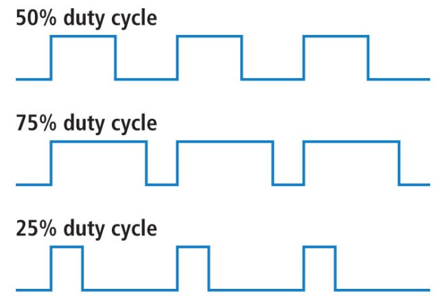
Because the LED is only outputting its signal for half of the time a 50% duty cycle is running, the light’s brightness will average out to 50% brightness over the time that we are looking at it.
Applying PWM to an LED
In order to see how PWM works and control it manually, we are going to write a new code, which will function like a combination of the AnalogInOutSerial and Fading examples that are built into the Arduino software. AnalogInOutSerial.ino reads values from the potentiometer, maps them to a value, and displays that value in the serial monitor. Fading.ino applies PWM to an led for an automatic change to the LED’s brightness. By combining them we will be able to manually change the PWM duty cycle and see this change in the serial monitor.
Start by opening up both of the mentioned examples as well as a new file. We will start by copying everything in the
AnalogInOutSerialexample into this new file so that we can save our version.- you can name this file whatever you want.
Now we will start to add elements from the
Fadingexample to our code. Begin by adding variables for the LED pin and LED brightness. You can copy them from the fading code or just type them into the new file.const int ledPin = 9; int ledBright = 0;- The pin you select needs to be capable of pulse width modulation. These are pins with the symbol
~before the number. On the Arduino Uno board, these are pins 3, 5, 6, 9, 10, and 11.
- The pin you select needs to be capable of pulse width modulation. These are pins with the symbol
The next step is to add the mapping. Add the following line into the beginning of the
loopfunction:ledBright = map(sensorValue, 0, 1023, 0, 100);- This take an input (the value from the sensor pin which will read the potentiometer). The second and third arguments are the original range of that input, and the final arguments are the new range that the values will be scaled to. Remember that the duty cycle goes between 0% and 100%, so having a range of larger than 0-100 won’t affect the brightness of the LED.
Now we need ot actually write the value. Add this line below the
delay(2)line from the starting example:analogWrite(ledPin, ledBright);- This takes our mapped value from the potentiometer and writes it to the LED pin we specified earlier.
This step is technically optional. Add the following lines in between
Serial.print(sensorValue);andSerial.print("\t output = ");Serial.print("\t Brightness % = "); Serial.print(ledBright);- This will show the values and duty cycle percentage in the serial monitor while the code is running.
Once your code is ready, you can flash it to your board. and move on to building the circuit.
After following all of these steps, your code should look like this:
Building the circuit.
The circuit needed to interact with this code is almost identical to the one shown at the beginning of this lesson.
Connect a potentiometer to power and ground, and the center pin to A0. Then wire in an LED wit the power coming from PWM pin 9 (or whichever PWM pin you selected in your code.) use the diagram below if you need a visual guide.
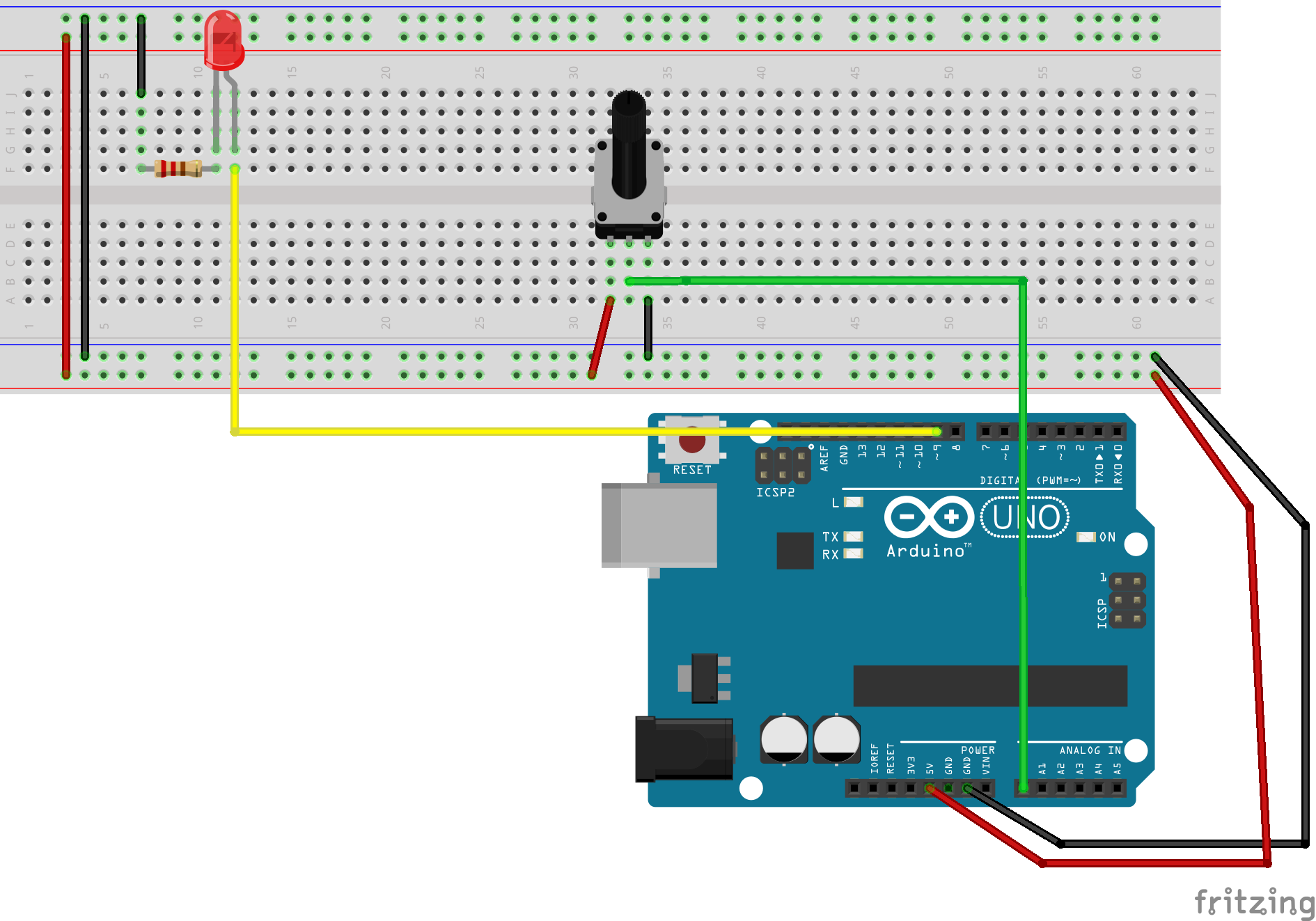
Once the circuit is built, connect power and you should see the LED behave like in the video below. Now with no rapid blinking.