What is a Digital Signal?
A digital at its simplest signal is a signal that exists in a boolean state. It is comprised of 2 values: on/off, 1⁄0, high/low, etc. Some kinds of digital signal, such as audio, can have a higher bit-depth with more potential values. However the digital signals we utilize for this class will all be built out of this high/low structure.
Digital Inputs & Outputs
We can set our arduino boards to send or receive digital data through their digital pins. If you are using the Arduino Uno board, there are the pins labeled DIGITAL 0-13. a single pin cannot both receive and transmit data at the same time. In order to tell our Arduino to send or receive the information through a certain pin with the use of the functions pinMode() digitalRead() and digitalWrite().
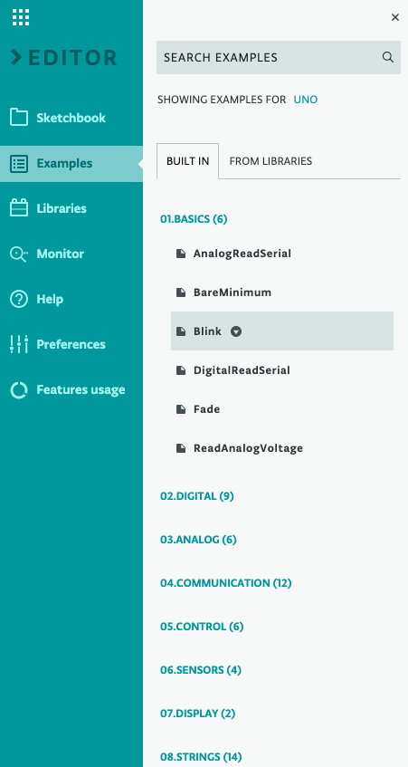
In order to do this, lets open up the Arduino web editor and open up the example labeled “Blink”.
Arduino boards contain a built in LED that this code will automatically turn on and off. We can use this LED to make sure that everything is working first before we begin creating circuits.
In the code, we can see that pinMode() is used to set the built in LED pin to an output inside of setup(). Inside of loop() we see four lines:
  digitalWrite(LED_BUILTIN, HIGH);   // turn the LED on (HIGH is the voltage level)
  delay(1000);                       // wait for a second
  digitalWrite(LED_BUILTIN, LOW);    // turn the LED off by making the voltage LOW
  delay(1000);                       // wait for a second
Remember that loop() functions like draw() in P5; it repeats the code inside of it repeatedly for as long as the code is running
Because we set the LED_BUILTIN pin to output, we can send values through the pin in order to influence objects wired into it. (in this case there are no external wires) Because this pin is digital, we can only send the values “HIGH” and “LOW”, which we do. We also utilize the function delay() which pauses the progression of loop() for the number of milliseconds given as an argument. so this example will set the LED_BUILTIN pin’s value to HIGH, wait 1 second, set the value to LOW, wait 1 second, then repeat. Setting an LED value to high turns on the light, and setting it to low turns it off.
If you connect your board and upload the code, you should see that the built in LED begins flashing like in the video below. Keep in mind that whatever code you send to your Arduino will overwrite the code previously stored on the board. The code currently saved to the board will start up automatically whenever the board receives enough power. (either from a USB connection or an external power supply) Below is a video example of what your board should look like once the code has been installed.
You may have recognized this code from the page Arduino SetUp. This is a simple code to check that your computer can properly communicate with your Arduino as it requires no extra components and is small in size.
Let’s Practice!
Try making sure that you can get the blinking LED code onto your Arduino board. You can try using the one we made in this lesson, or Arduino’s built in example. To access the examples, click File > Examples then choose which example file you would like to open.