Potentiometers and Sensors
Now that we have an idea of what an analog signal is, lets look at some hardware that we can utilize to control these signals in real time. Many of the components are variable resistors, meaning that they will act like a fixed resistor in terms of how they interact with the flow of electricity, but their Ohm value can change under different circumstances. A few of them are voltage dividers, which can be noticed by their three leads. (This is not a hard rule as some components have three leads, but fall into other categories.) In a voltage divider, the electrical signal is sent through two resistors. The different between the two resistors can be measures and used for a variety of purposes.
In this lesson we will go over details about some of the more common types of analog components and how to connect them to your Arduino board. We will not go into details about how to hook up every sensor however as many of the circuits are identical except for the sensor that is being used.
Voltage Dividers
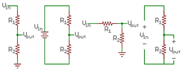
We can utilize multiple resistors to create a voltage divider. We may want to do this in order to lower the amount of voltage that is being sent to a component, or be able to change the voltage at will. When using a voltage divider we are measuring the amount of voltage present between the two resistor components. This setup looks like this:
There is a mathematical relationship between the resistance and voltage of a circuit. (called Ohm’s law) We can utilize that relationship in order to determine how much the voltage changes when the resistance is applied.
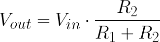
Since we know the initial voltage in our circuits is 5V, we can set certain resistances in order to arrive at various other voltages. Manually creating these dividers is relatively simple but can require multiple components, and when we have the limited space of a breadboard, that can be a problem. Luckily there are several sensors that function as voltage dividers and will help us avoid this problem. These sensors have three leads on them and are generally set up so that the output voltage leaves via the middle pin. Inside, the components are generally some kind of fixed resistance and another that can be varied. Because the voltage divider contains a resistor, is does not need another external resistor in order to function. However components that only have two leads do not divide the voltage, and often require a fixed resistor in order to function.
Potentiometers
A potentiometer, abbreviated pot, is a type of variable resistor that can easily be used to create a voltage divider. Potentiometers generally look like a knob or a slider and by adjusting the position of the knob or slider an internal wiper moves across a resistive material, changing the resistance the component has on the current. This change can either be linear or exponential depending on the hardware. The total amount of resistance also varies based on the hardware.
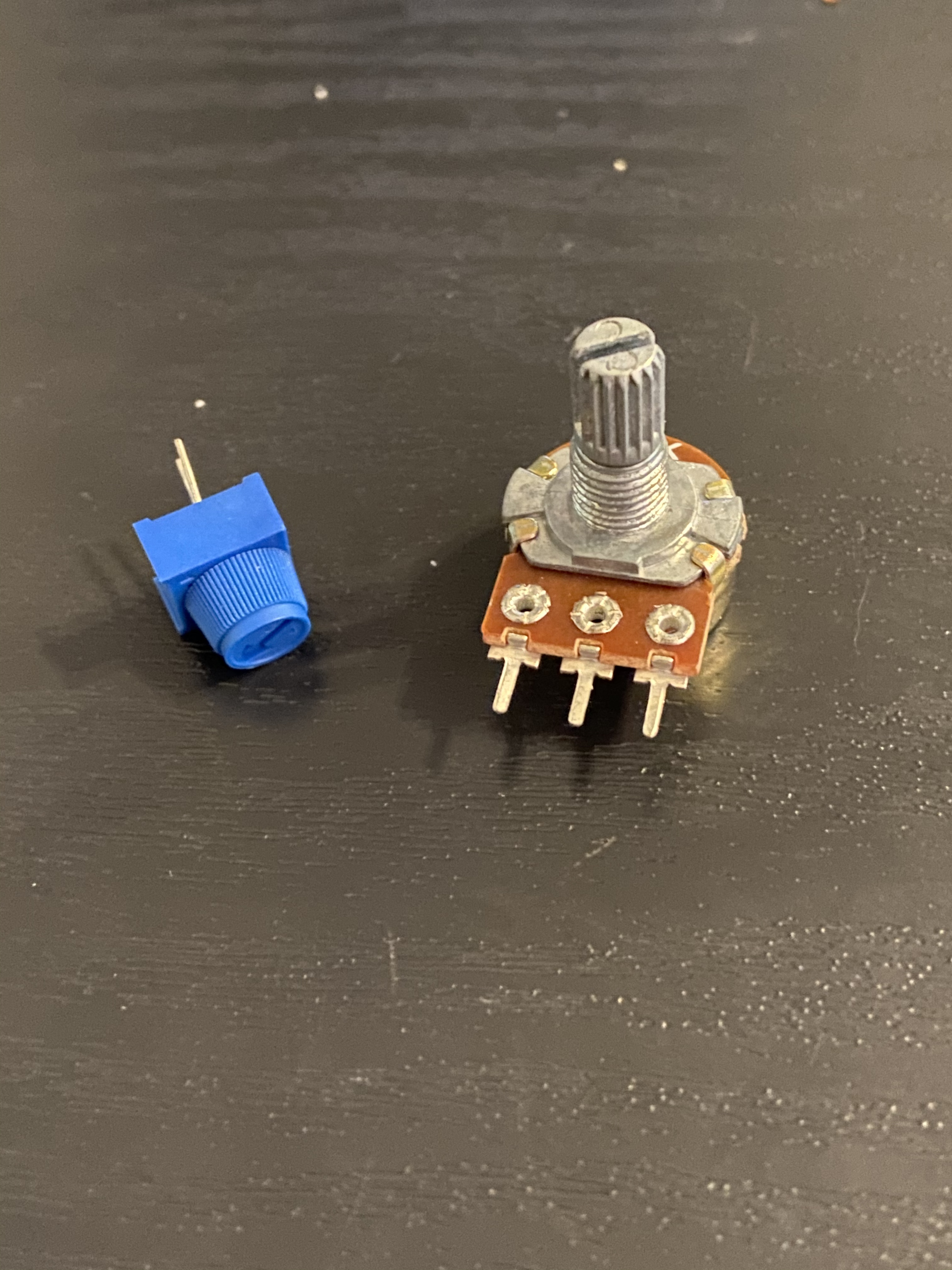
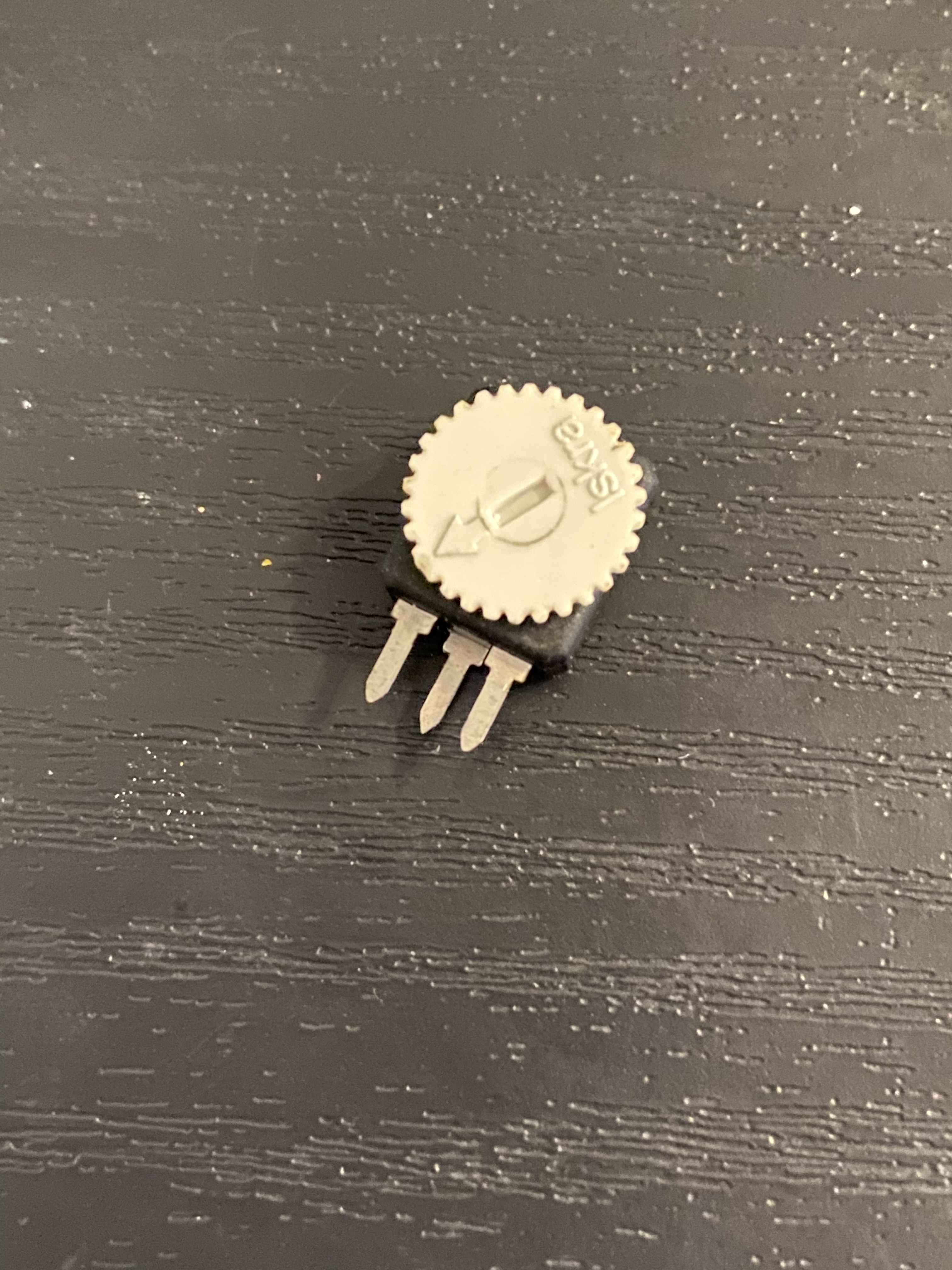
Pots have three pins as shown in the images. The outside pins connect to the positive and negative source voltage, while the middle pin is connected to the wiper. By connecting this middle pin to an analog input on our boards, we can read the voltage division as a value between 0 and 1023 with the analogRead() function. This value can be mapped to different ranges as needed.
Wiring up a Pot
In order to wire up a potentiometer, you need to connect its three pins to the appropriate places. The outside pins connect to the power and ground, while the middle pin should be connected to the input pin on your Arduino, like below
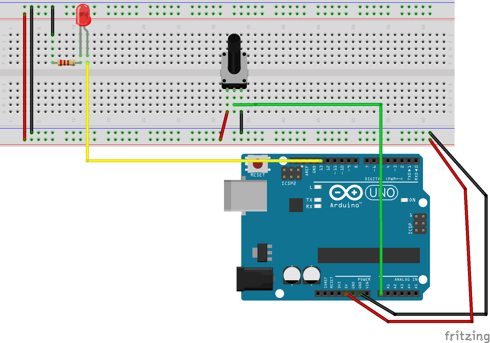
Next you can open up the Arduino code editor and upload the code below to the board. Once the code is loaded you will notice that the LED begins to blink. As you adjust the position of the pot, you will see that the LED’s blink speed either increases or decreases.
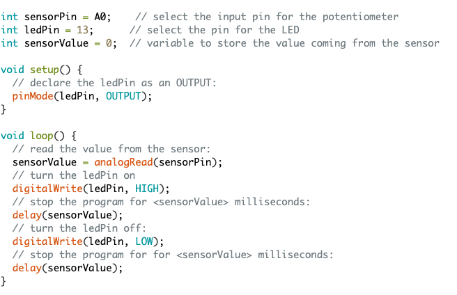
When turning the potentiometer, which direction causes the LED to speed up? Try taking the pot out and turning it around so the 1st and 3rd pins are switched. What happens now?
The circuit we just made is a voltage divider. Generally speaking, any of the sensors below that have three leads on them will also create a voltage divider. When wiring them up you can just remove the potentiometer and replace it with the new sensor and it will function identically. You can replicate the set up, but connect the component’s middle lead to a different pin on the arduino in order to have multiple voltage dividers on the breadboard at once.
Reading the Voltage Data
In order to see these numbers that represent the voltages being read by the Arduino, we need a few lines of code. add the lines below into your Arduino code in order to see the numbers.
void setup(){
    Serial.begin(9600);
}

void loop(){
    Serial.print(pin)
}
The pin value will be whichever pin you are connecting your potentiometer to. This can change depending on the values you want to read. Once the code is added, you can open the Serial Monitor and see the values being updated in real time. Later on we will be using the serial monitor to communicate with other programs.
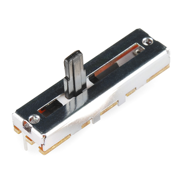
Other Kinds of Potentiometers
Most Arduino kits come with rotary pots, but potentiometers with a sliding mechanism are also common. Trim pots a a sub category of rotary potentiometers that are small in size and often used for calibration and other finite adjustments. They often need a screwdriver in order to turn. There are also components known as soft pots. These potentiometers function similarly to force sensors in the face that they react to pressure, however instead of changing their resistance based on the amount of pressure being applied, the soft pot responds to where the pressure is applied along its length.
Sensors
A sensor will function similarly to a potentiometer, however their changes in resistance are reactions to various conditions instead of being directly caused by human intervention. These conditions include light level, direction, movements, location, sound volume, temperature, etc. There are far too many types of sensors in order to name them all right here.
Light Sensor
Also called Photoresistors, a light sensor reacts to the electromagnetic radiation given off as visible light. As light hits the (often) red film behind the metal points, the resistance between them lowers.
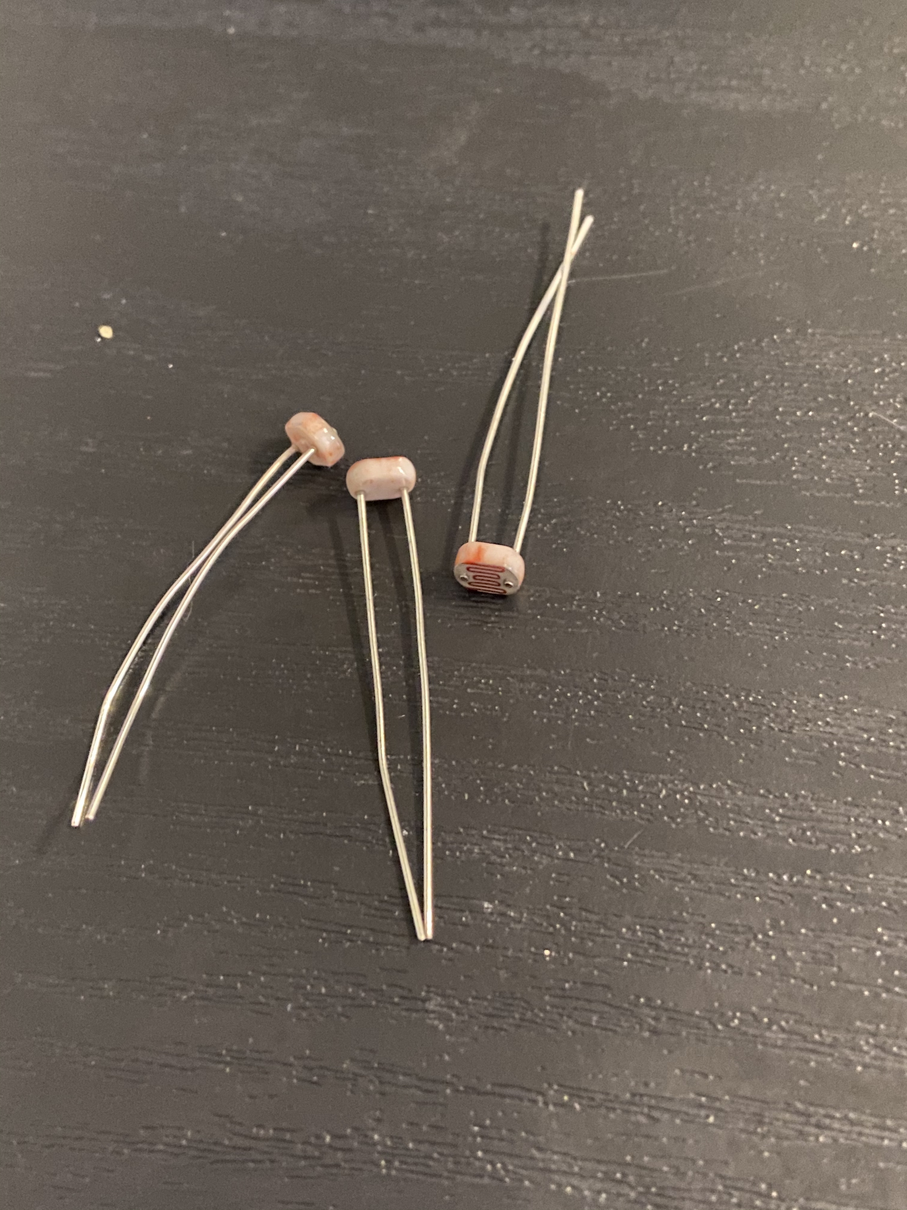
Many of the smaller photoresistors tend to be less accurate than some of the other sensors on this list, but they can still be used in a large variety of situations.
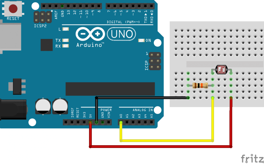
Using a Light Sensor
We can wire up a photoresistor like shown in the image below. By measuring the analog values with our Arduino’s analog pins and the analogRead() function we can apply the values coming from this sensor to various other components. Just don’t forget the 10K resistor.
These 2 lead sensors function as a resistor that can change their resistance based on their reaction to an external stimulus. For all of the variable resistors shown below you will need an additional fixed resistor in order to function properly. Without one the voltage could overload the sensor. The exact size of the resistor will vary depending on the component being used. Be sure to double check your kit for more details.
Force/Pressure Sensor
A force or pressure sensor looks like a flat version of a photoresistor. The component is comprised of two metal leads suspended in a resistive fluid and encased in plastic. The specific shape and size can vary, but they tend to be relatively small and either circular or rectangular in shape.
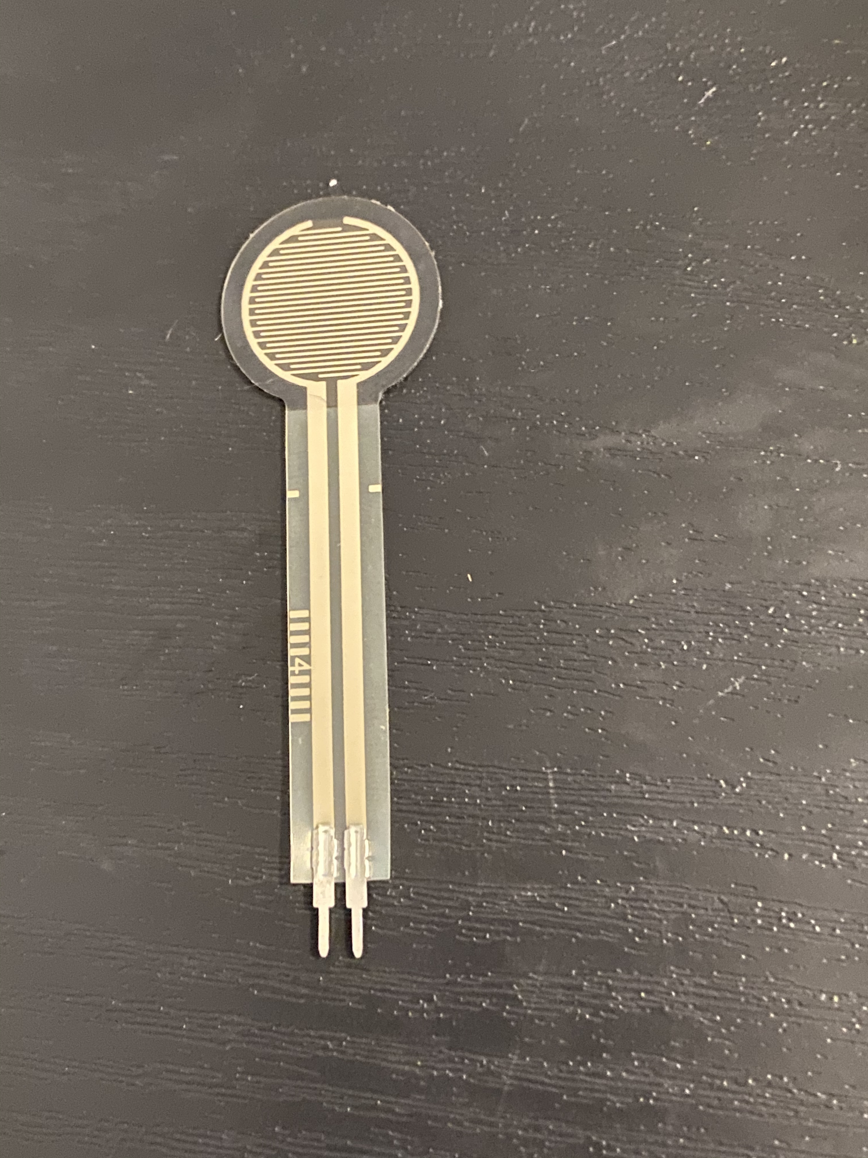
By applying pressure to the sensor, the fluid is displaced, decreasing te resistance. The more pressure that is applied, the more the resistance if lowered. There are different pressure sensors that can respond to varying levels of pressure. These sensors are great for general measurements, but lack the resolution to be used for accurate, fine-tuned pressure monitoring.
The circuit for utilizing a force/pressure sensor is identical to the one used for a light sensor, just replace the sensor.
Distance Sensor
Distance sensors are a little unique on this list because they have their own built-in circuitry. They are set up to function like a voltage divider however, which makes them easy to utilize as a means of data input.
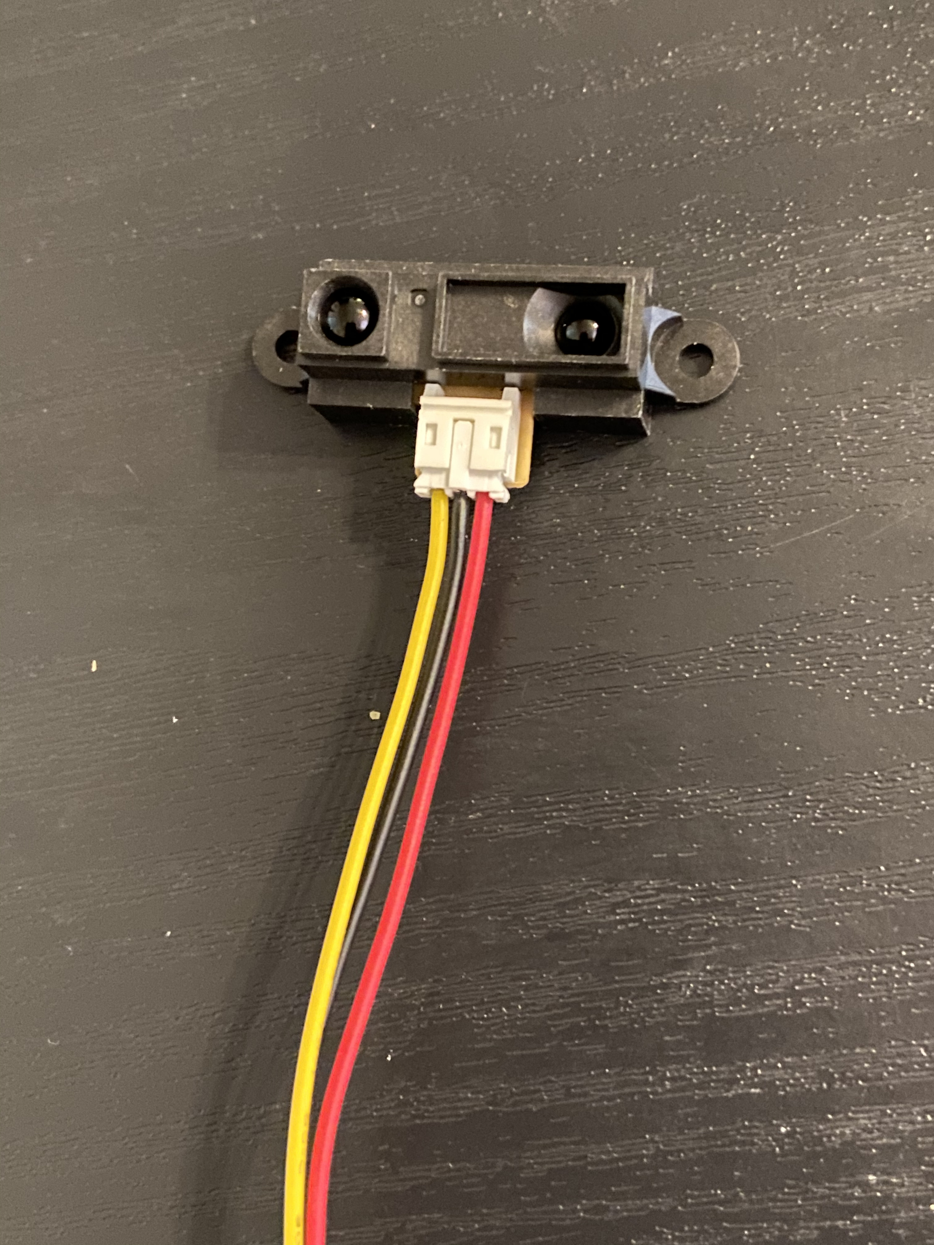
An infrared beam is sent out of one lens and when an object is within the range of the sensor, the beam will be reflected back and be detected by the second lens. The built in circuity calculates a value based on the amount of time that this reflection took place and adjusts the resistance of the unit accordingly.
We can connect this sensor in the same manner as a potentiometer, but we cannot change the direction that voltage moves through the sensor because of the on-board circuit board.
Tilt Sensor
Tilt sensors have a variety of appearances and various functionalities as well. Generally, a tilt sensor can measure how much the sensor is offset from ‘level’. More expensive sensors can measure the tilt in multiple directions and give a range of values. Cheaper models only measure one direction, and output a digital HIGH/LOW signal that changes when the sensor’s tilt passes a certain threshold.

These sensors contain a small ball. When the tilt is large enough, the ball will roll to the end of the sensor and make an electrical connection.
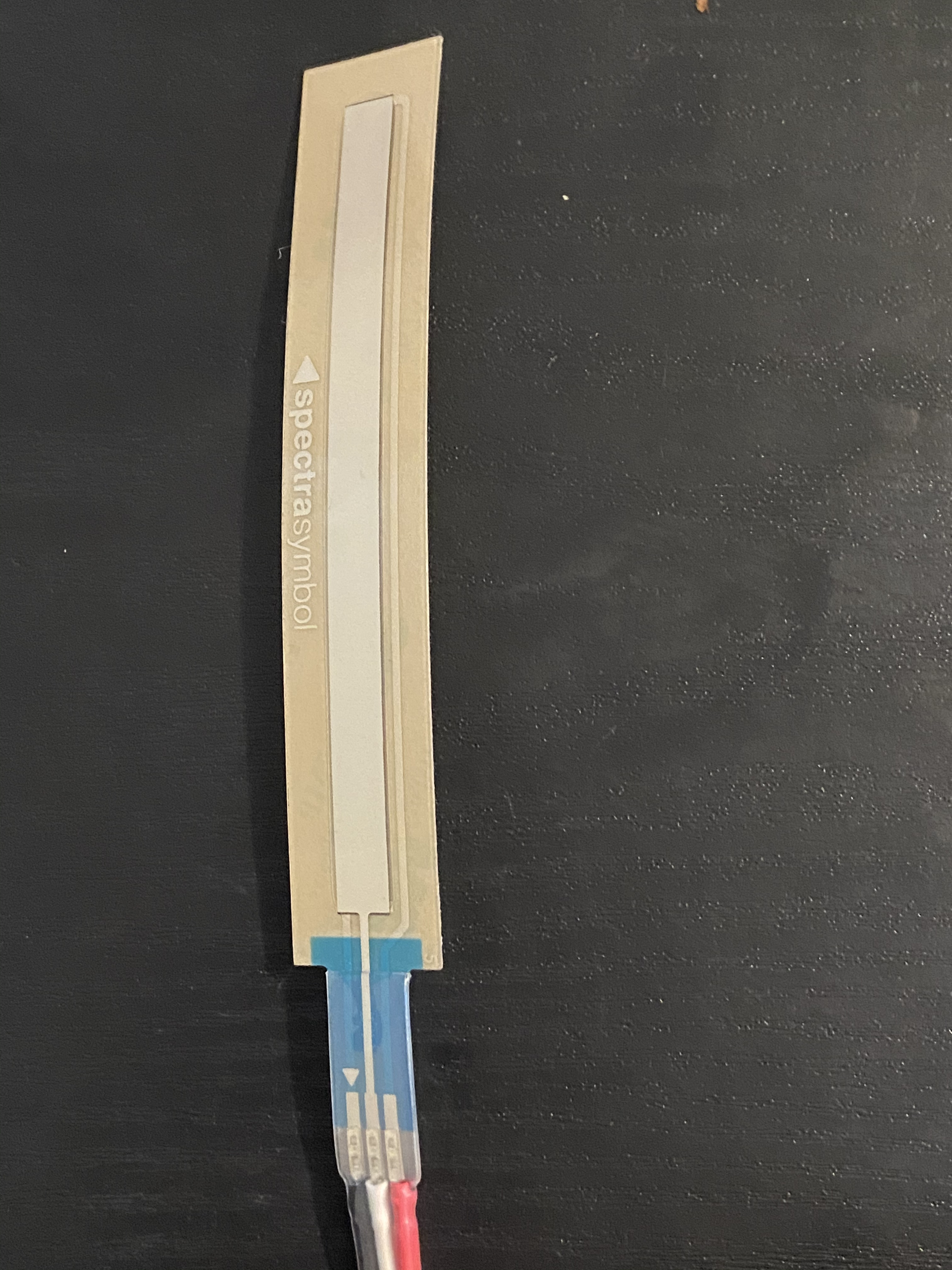
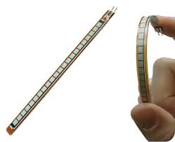
Flex Sensor
A flex sensor functions similarly to a pressure sensor except that it detects the force of the sensor bending in a specific direction.
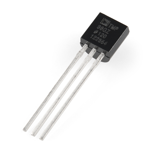
Temperature Sensor
Temperature sensors react to the ambient temperature around them and are the core component to many digital thermometers. These sensors have a variety of appearances, and output a number value that will change along with the temperature of the sensor. These numbers may be scaled to a temperature scale within the sensor, or code may be needed to achieve this within the program; it depends on the sensor.