Adding Buttons and Switches
Now that we can build a simple circuit, lets look at how we can add in a button and a switch to both turn an LED off and on.
Buttons and Switches
Buttons and Switches have a similar deigns and purpose: To route electrical to different places based on their states. The main difference is that buttons restore to their defaults state once they are released, and a switch will remain in its current state until it another person uses it.
This is not a universal rule as buttons and switches that behave differently can be purchased, as well as stitches with multiple potential states outside of ‘on’ and ‘off’. However the items common to the recommended Arduino kits for this course, as well as the majority of available hardware fits into these definitions.
Buttons and switches can come in various sizes and styles depending on their intended use. In this lesson we will be using both a button and a switch as a toggle for the LED circuit that we built in the last lesson. If you need to, revisit that page for instructions on how to build the starting circuit.
buttons/switches to connect electrical current
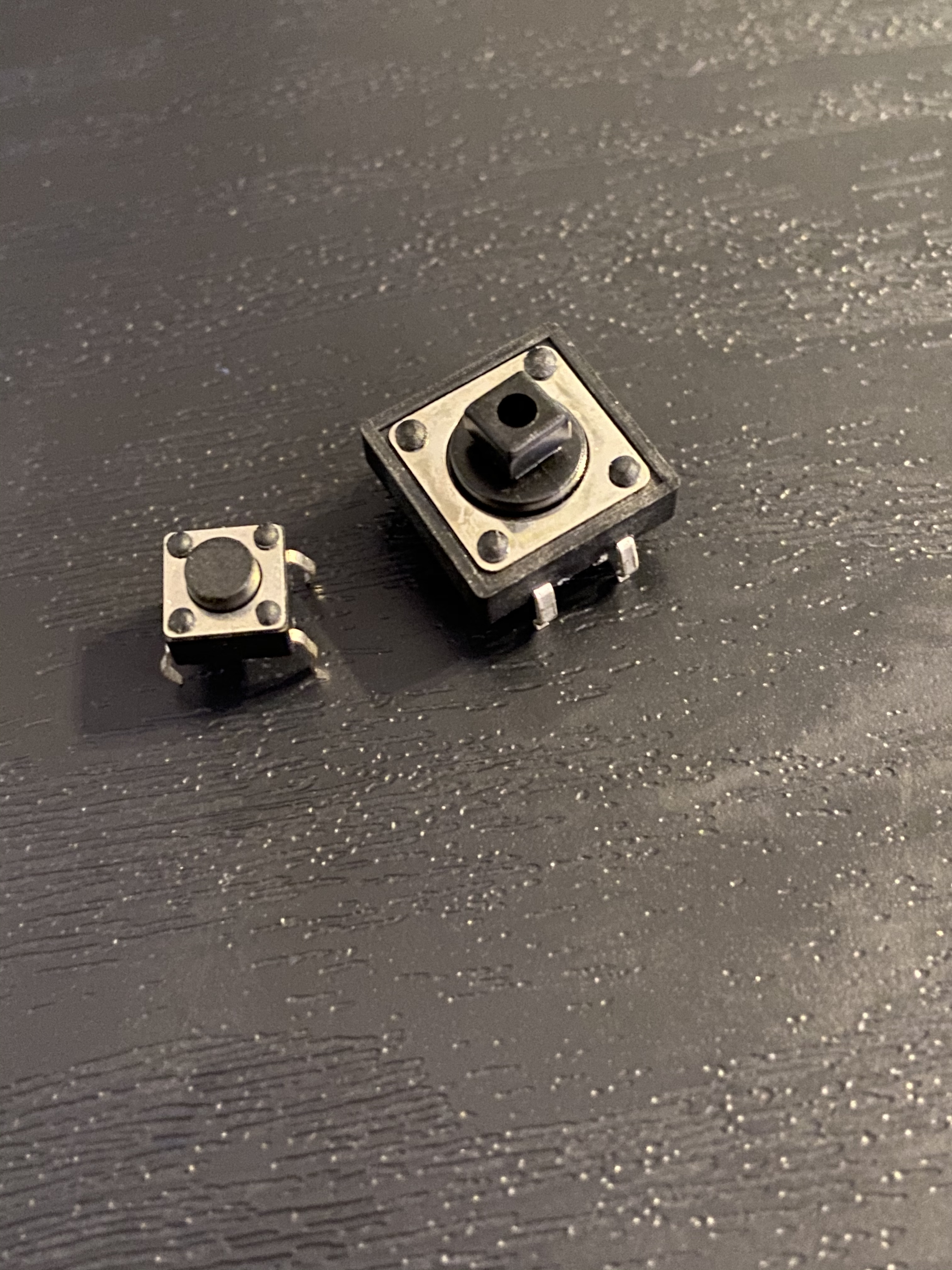
We will be using both a button and a switch in order to connect the electrical current needed to turn on an LED. But first lets dive a little more into what is happening. Below is the diagram for a basic push button like the one included in Arduino kits.

The electricity will want to flow between the wires on the bottom of the image, however because a physical connection is needed the signal cannot more forward to complete the circuit. To fix this, a user will have to push the button which will cause the connection to occur and allow the circuit to be completed. Once the user lets go of the button it will return to its default state and break the circuit.
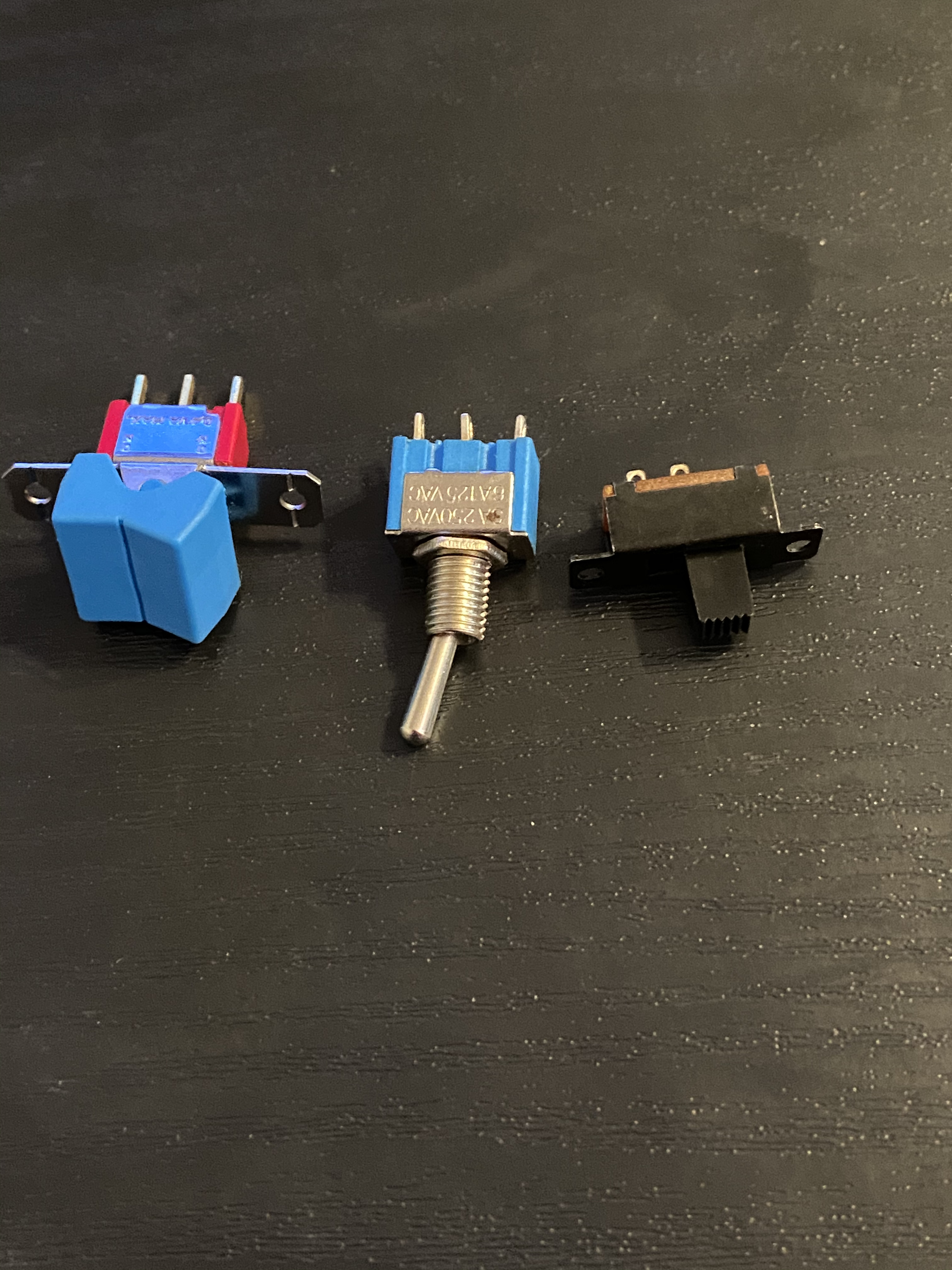
A switch will function slightly differently than a button.
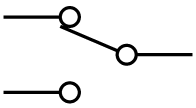
The incoming electricity will be routed to one of two (or more depending on the switch) potential outputs depending on the state of the switch. Flipping the switch will change where the electricity is being routed. In the example below, we will either route the electricity to complete the circuit, or to nowhere, breaking it. However, it is possible to set up all of the potential outlets to complete a circuit. However this will require the switch to be placed before the components that will we controlled, instead of after.
Building the Circuit
Button
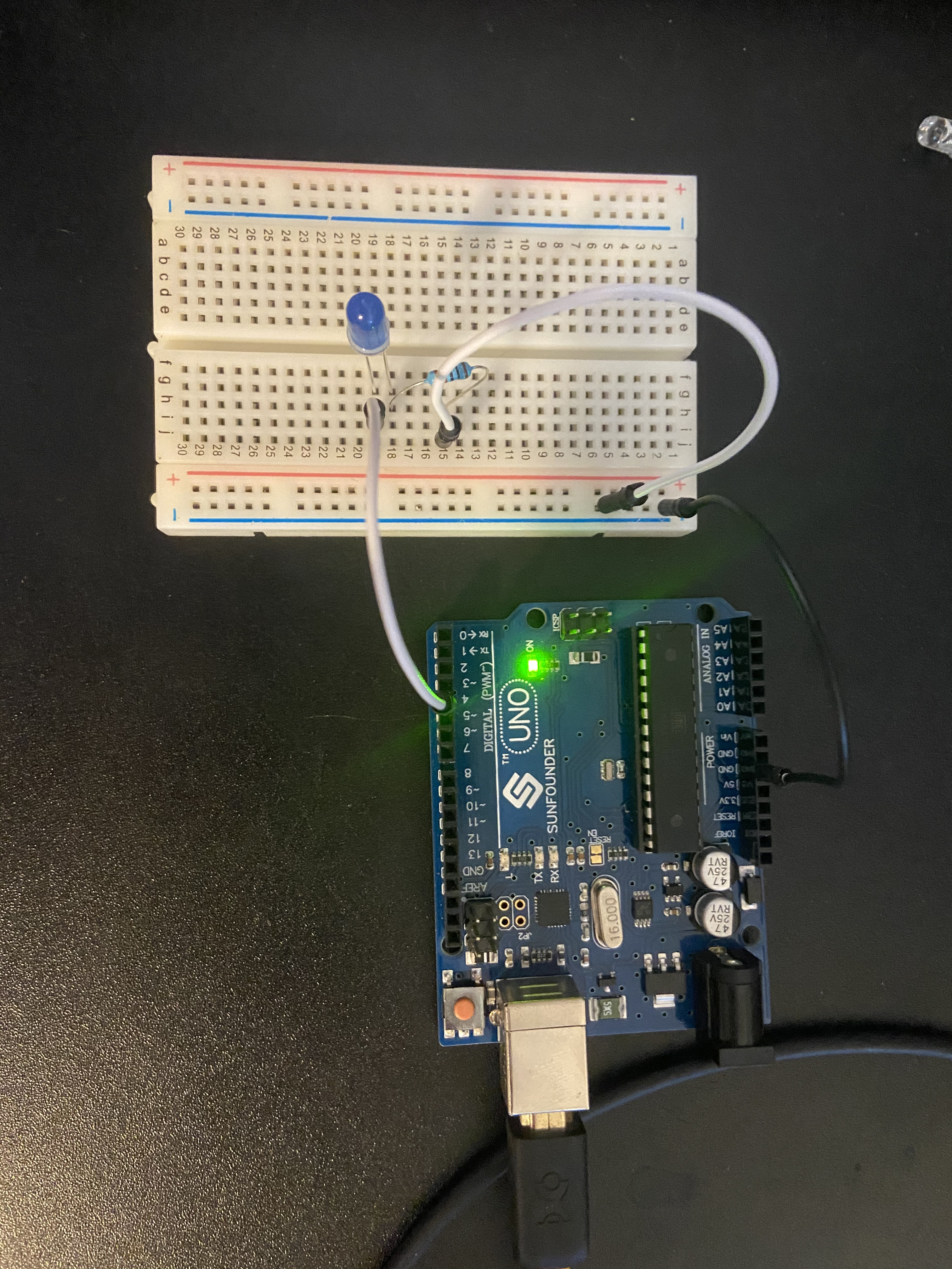
Now we will build the new circuit. Begin with the previous lesson’s final circuit, which is shown below. A live-patching style tutorial video for how to achieve both the button and switch circuits is located at the end of this section
Begin by disconnecting the power cable from the Arduino’s pin 4. This will break the circuit and stop you from accidentally creating a short circuit. It is always a good idea to disconnect from the power source when building a circuit ESPECIALLY if you are connected to a power outlet and not a battery or computer.
Because we are just breaking and connecting the circuit in this example, the button/switch can be placed anywhere along the electrical pathway. In the images below, they have both been placed after the LED and resistor, but before the signal moves to ground.
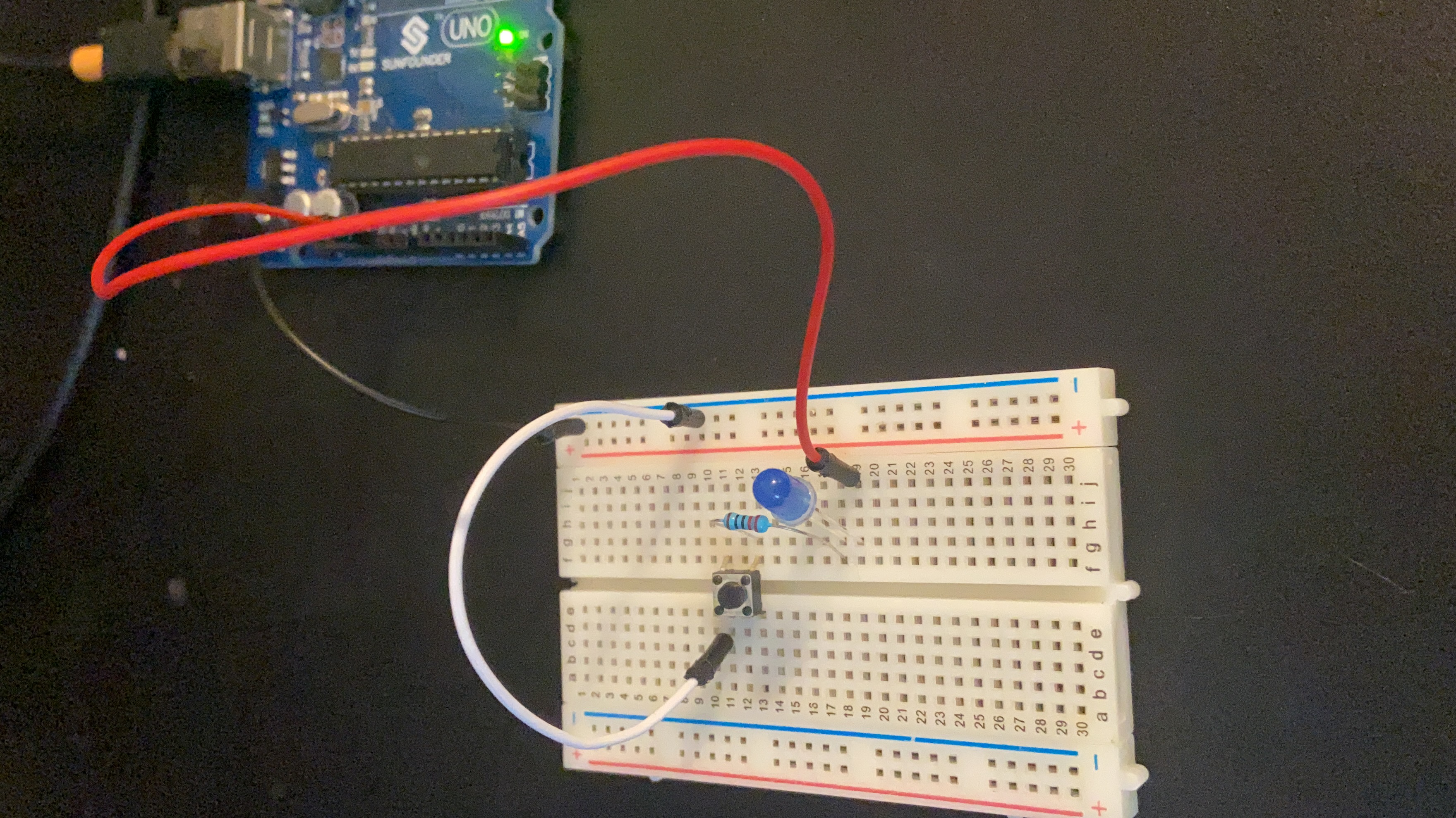
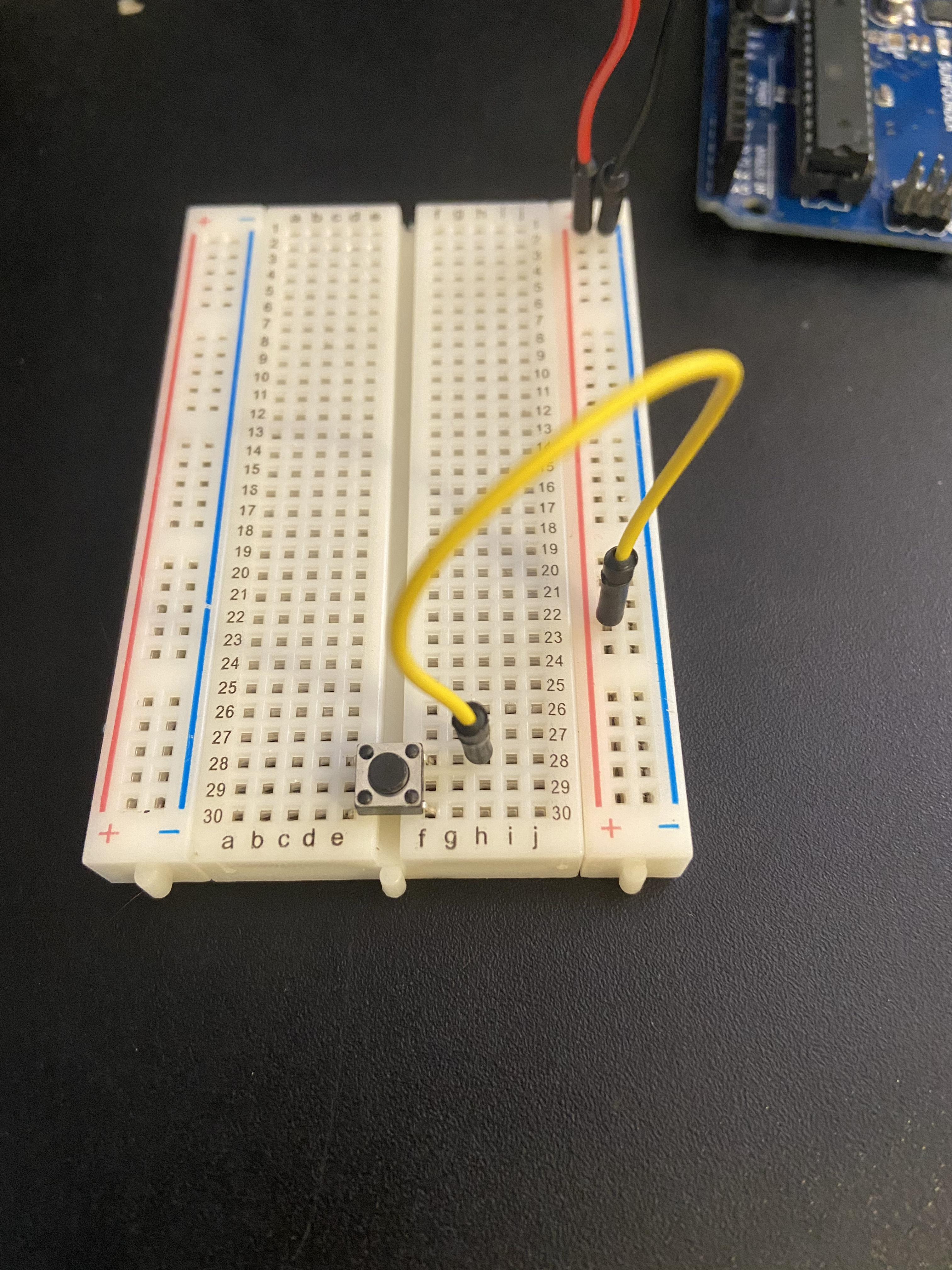
The second step is to attach your button to the breadboard. Utilizing the gap that runs down the middle is aa good way to avoid accidentally connecting to any other elements as the current will not travel to the far side of the board automatically. In the image below, the resistor is used to connect to the button, but a jumper can be used as shown in the tutorial video.
Next remove the ground end of the white cable and connect it to the button. Add an additional jumper cable and connect it from the far end of the button to ground.
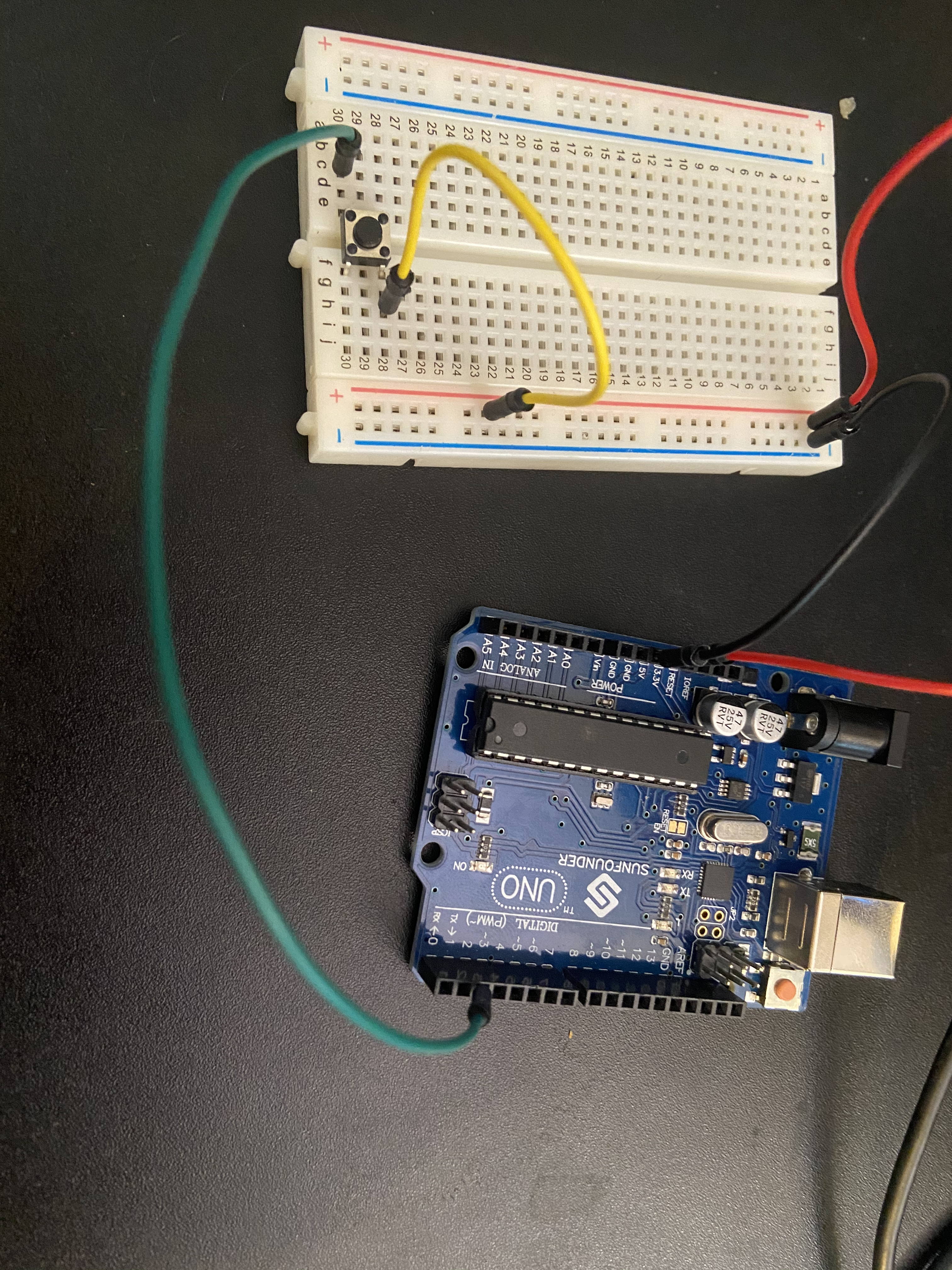
You can now reconnect your power cable to the 5V pin on the Arduino. Your circuit should look like this:
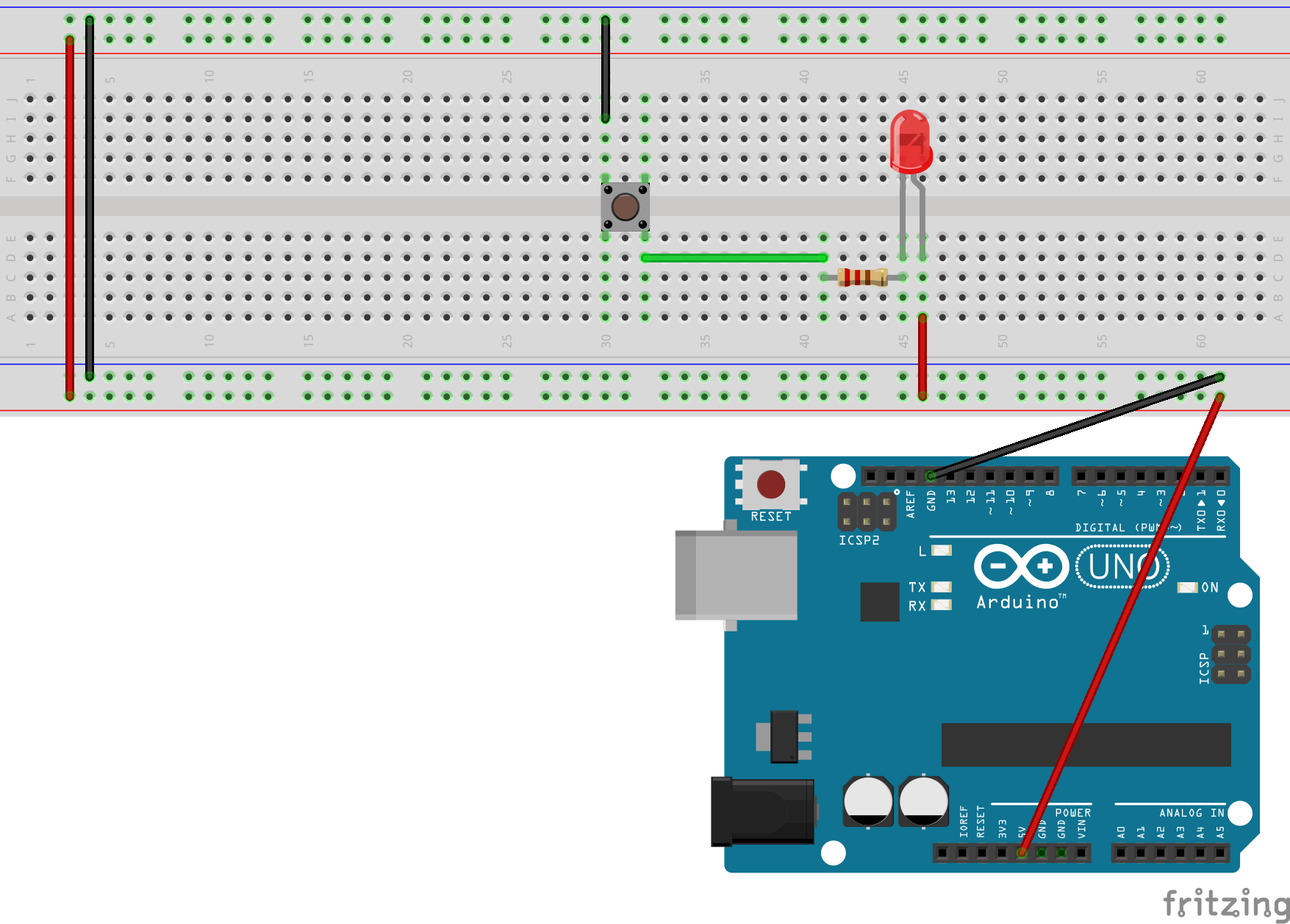
Notice how the input and output are located diagonally across the button? Many buttons are arranged this way internally. Unless you have the internal diagram for the buttons, there is no way to know if your button is arranged diagonally or not. Be sure to try different combinations and orientations if your button does not work the first time.
Here is a short video showing the working circuit pictured above. Notice how the light only turns on when the button is pressed. These buttons help indicate this with an audible click.
Switch
Now lets change our button to a switch. Start by removing the button, and connect the output from mhe resistor to the middle pin of the switch. Using a jumper cable is recommended unless you have ample room on your breadboard.
From there you can connect either the top or the bottom pin to ground so that your circuit looks like the image below.

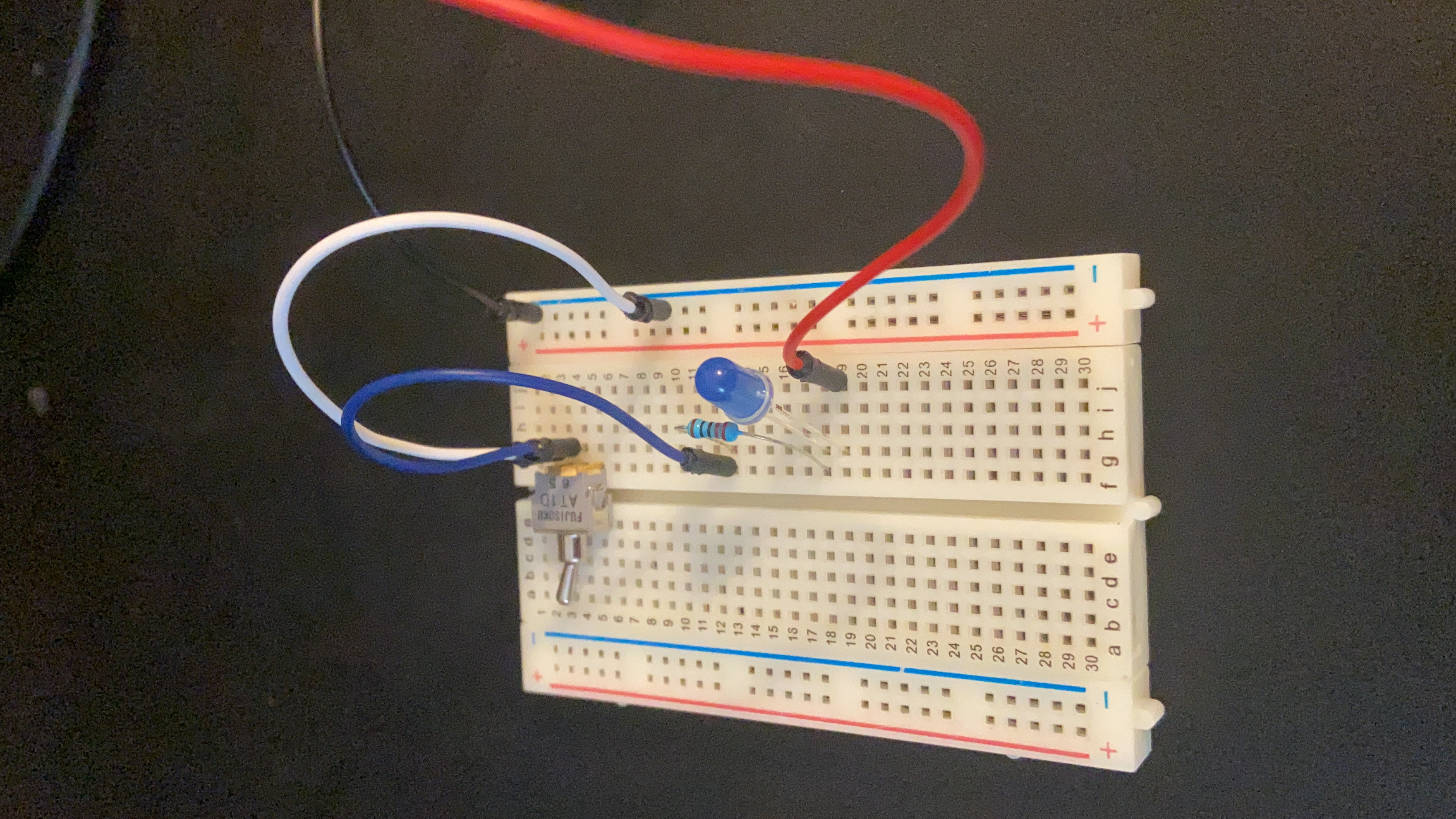
By changing the switch from the up or down position we are now either completing or breaking the circuit. Below is a short video showing the circuit pictured above in action. Notice how the light will remain on until it is turned off and vice versa. This is a simplified version of what happens when you turn a light switch on and off in your home.
As mentioned previously, you can utilize a switch to change between multiple states. The video below illustrates that by using the same switch to change between two different LEDs.
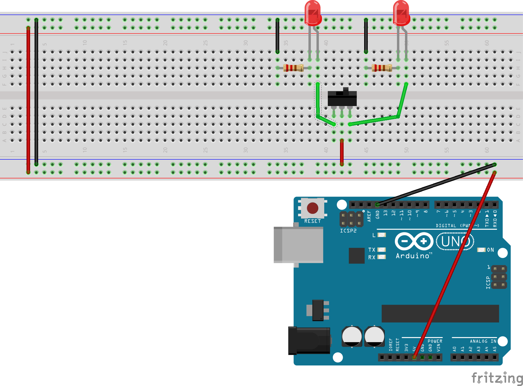
This time notice that the power supply is is being fed into the switch, and the output pins are connected to the LEDs which each have their own resistor and connection to ground. No matter which state the switch is in there is a complete circuit so a light will always be on. We are now able to route the electricity to a different pathway before it reaches the LED. Keep in mind that if you try to recreate this, you may need to reverse the direction of your LEDs. Remember, the longer lead is the positive end, and the shorter one connects towards ground.
This video is a live-patching tutorial that creates the circuits outlined so far in real-time. check it out for help creating the circuits.
buttons to set values with digitalRead()
Our next step will be to receive data from a button in order to toggle a light. The final result will be the same as our previous code, but allows for a larger array of possibilities that we will explore upon in chapter 12.
The Code
Because we will be receiving digital data instead of transmitting it like in our original circuit, we will now have to go back to the Arduino code editor and re-write some new code to send to our board. Remember that this process will overwrite the code that we currently have on the board (A modified version of the ‘Blink’ example if you are going through this book in order.)
Start by opening the Arduino Code Editor. This can be either the online editor, or the downloadable application. Instead of beginning from a tutorial code, lets build this one from the ground up. Open a new file and rename it so that you can find the file later.
Start by creating three new global variables as shown below. You do not have to add the identifier const to the first two variables. However, because these will not change at all when our code is running so we can identify them as ‘Read Only’ with this keyword to prevent any accidental changes. You can change the buttonPin variable to be any digital pin on your arduino that you want, but for this example you will need the ledPin variable to be set to 13. Most Arduino boards contain a built in LED and on the Uno board, that LED is connected to pin 13. So when pin 13 is set to HIGH the LED will light up, and when it is set to LOW the LED will turn off.
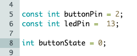
The third variable will measure the whether or not the button is pressed, and cannot have the const identifier because it will change.
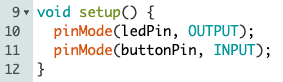
Next we need to specify that the buttonPin, which we are assigning to pin 2 in this example is an input, and the ledPin (pin 13) is an output using the pinMode() function inside of void setup()
Moving on to the loop function, we need to tell the arduino to read the current state of the buttonPin and store that value inside of the buttonState variable. That line looks like this;
buttonState = digitalRead(buttonPin);
The final step in the code is to create an if/else statement that tells the code how to react to the value of the buttonState variable. When the button is pressed it will pass signal to the pin. When this signal is detected it will store a 1 in the variable. Otherwise it will store a 0 when the circuit is not connected. These 1s and 0s can also be read as the values HIGH and LOW respectively. Using this information, we can build the following conditional statement inside of the loop function:
 if (buttonState == HIGH) {
    digitalWrite(ledPin, HIGH);
  } else {
    digitalWrite(ledPin, LOW);
  }
}
Now we can send the code to our arduino and move on to building the circuit. Incidentally, the exact process we just went through created the built in “Button” example, which is located in the digital section of the built in examples. You can open this code in the arduino web editor in order to see the schematics and layouts for the circuit we are about to build.
The Circuit
Once you have successfully added your code to the Arduino board it is now time to build the circuit.
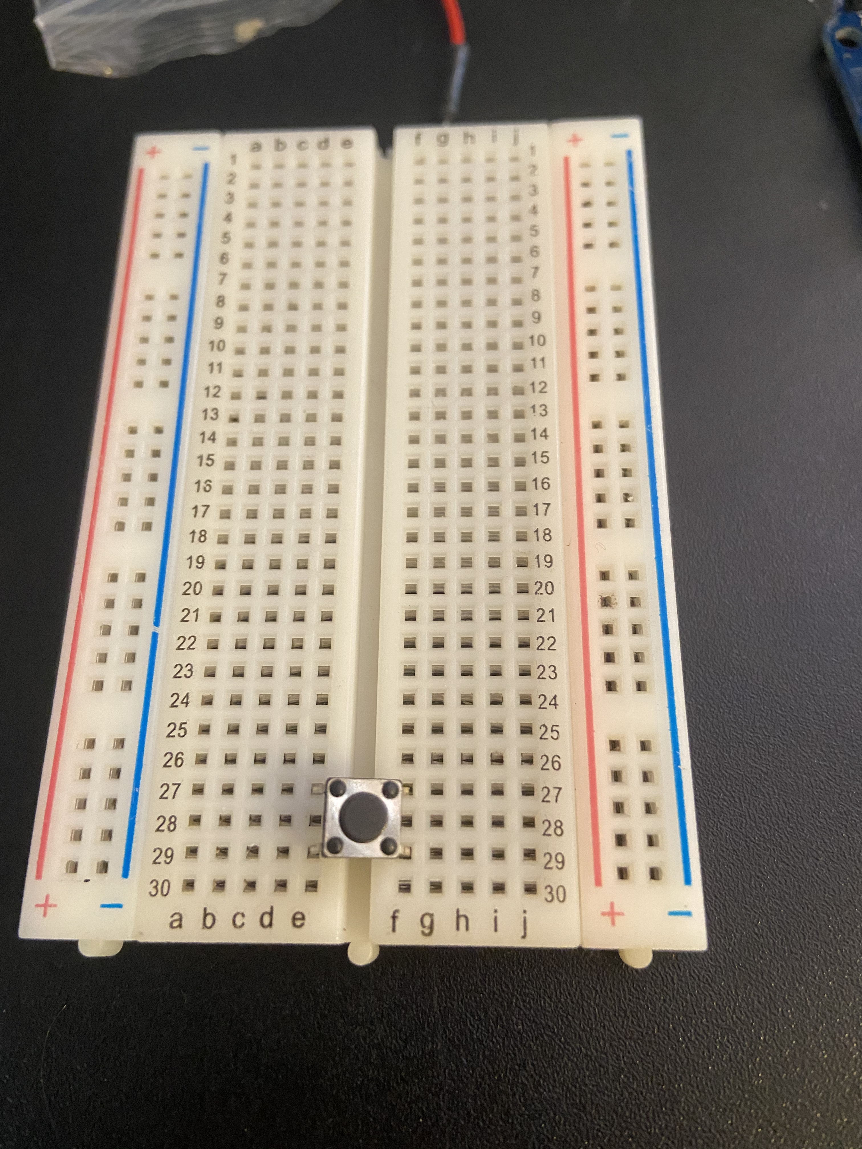
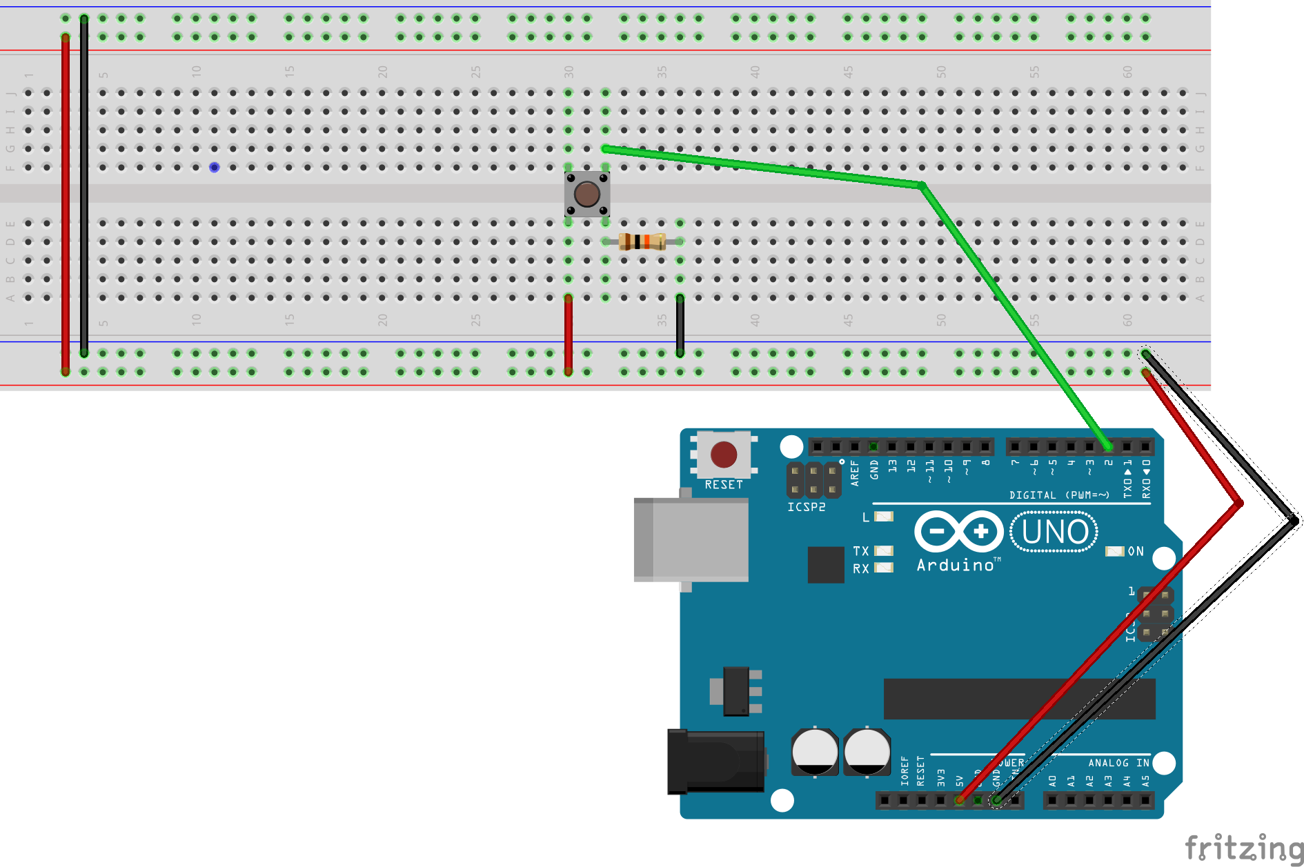
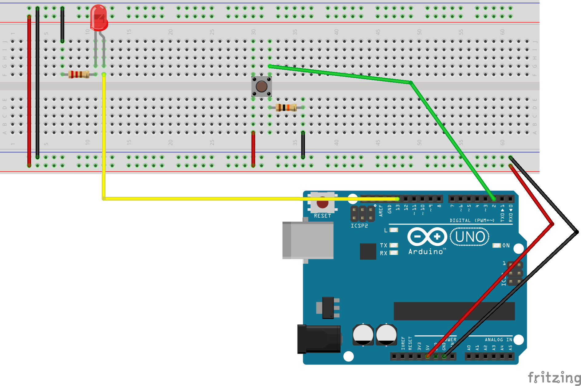
We will start by connecting the button to the middle of the breadboard like shown.
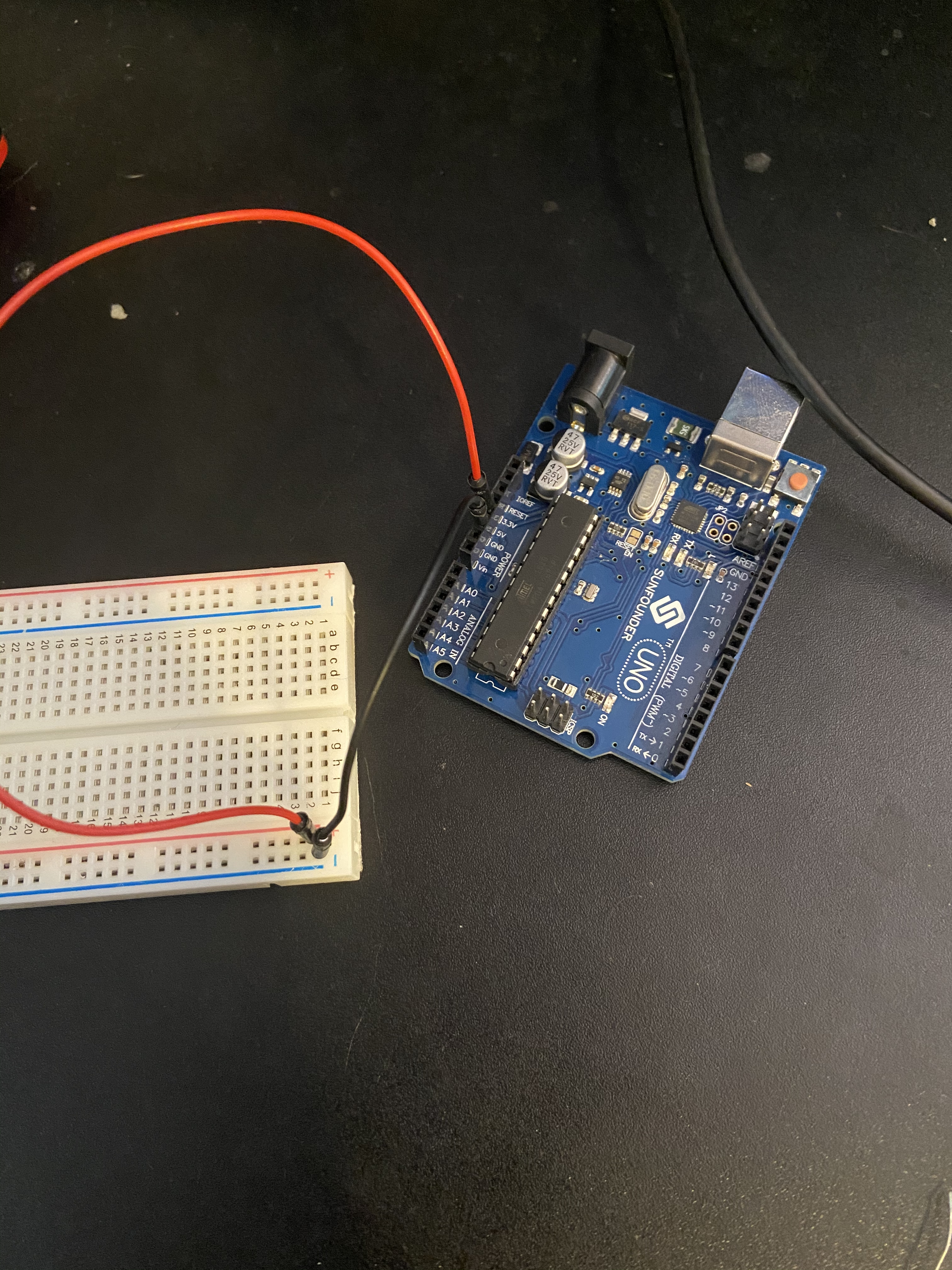
Then connect the 5V and ground pins ont he arduino to the breadboard. Notice that the arduino is not connected to any power source at this time.
The next step is connect the power to one side of the switch as shown.
Followed by connecting the opposite side fo the switch to pin 2 on your arduino (or whichever pin you set the buttonPin variable to). Notice that this is diagonally across from the button’s input.
The last step is to include a resistor so that the LED is not overloaded. Arduino recommends utilizing a 10K Ohm resistor, shown below.
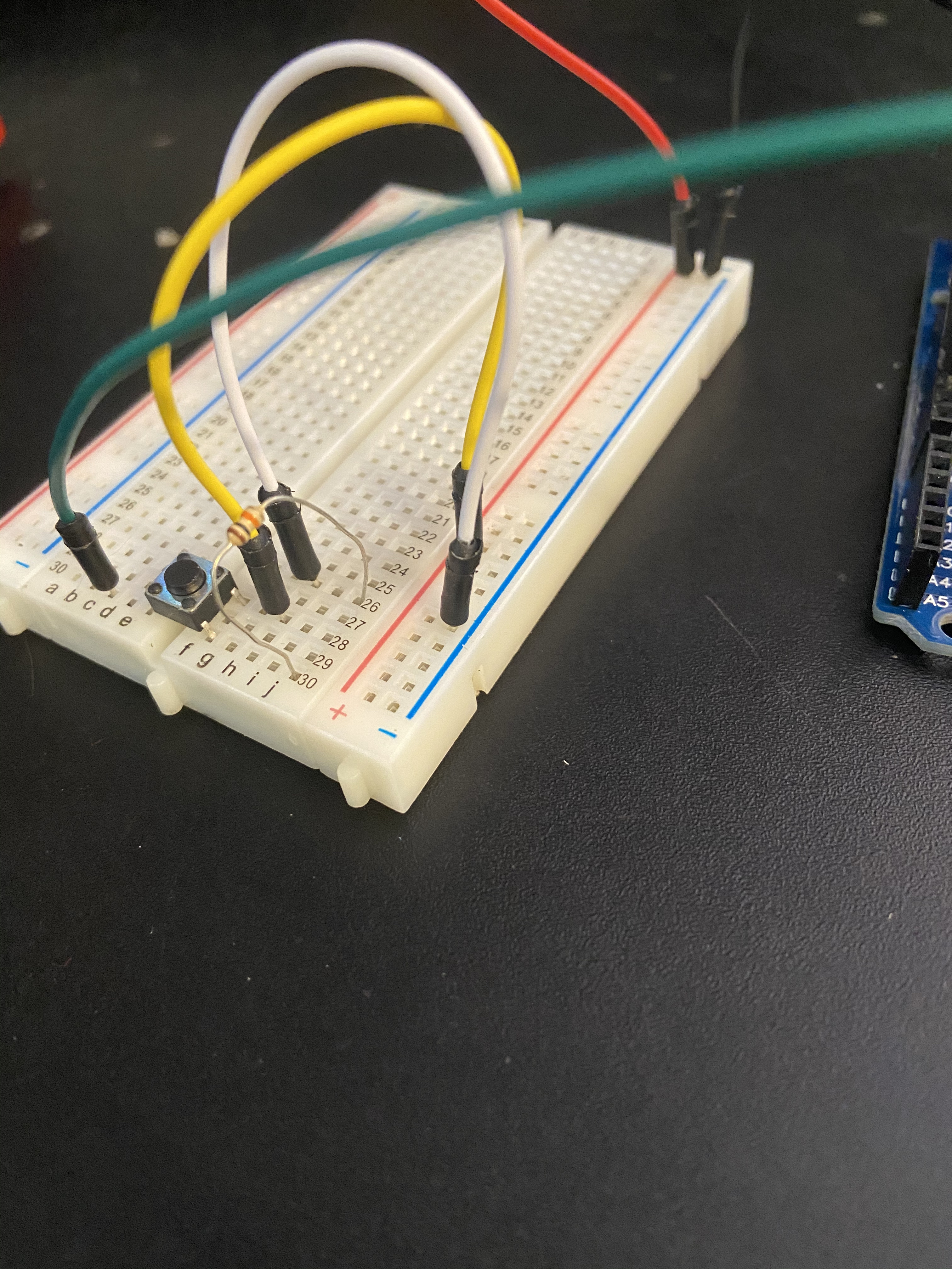
At this time you can connect your Arduino to power and press the button. You should see the built in LED turn on an off like in the video below.
While your arduino is connected to the computer and running this code we can tell the computer to display the value of the buttonState variable so we can keep track of it in real time. Open the serial monitor in the arduino code editor. We can see the state of the buttonState variable change in real time. This will be useful for troubleshooting and determining various settings later in chapter 11. By default you will not see anything in the monitor so we have to add two lines of code to our project. We need to first add this line to the setup function:
Serial.begin(9600);
And this line to the loop function:
Serial.println(buttonState);
Once we have these line in the correct place we can upload the code to our Arduino and see the values update in real time. The argument for the Serial.begin() command is how frequently the signal updates per second. and is indicated in the monitor under ‘baud’. Try pressing the button with the serial monitor open now. It will automatically connect to the same serial port as your Arduino. You should now see a series of 0s that change to 1s whenever the button is held down.
Applications
So why go through these extra steps just to create a toggle when it is much easier to just build something like our first code in this lesson? The answer is that in this version we are now reading the electricity level and responding to it instead of breaking the pathway. Like previously mentioned, most Arduino boards have a built in LED attached to pin 13. With the code we have now, we can connect the pin 13 output to an external LED circuit like shown in the video and image below, you will be able to toggle additional lights as well. And not just lights, anything connected to this pin can be triggered with just a single button press.
Lets go back to the code real quick to wrap this up. Below is the conditional statement that we added to tell our board how to react to the buttonState value.
 if (buttonState === HIGH) {
    digitalWrite(ledPin, HIGH);
  } else {
    digitalWrite(ledPin, LOW);
  }
}
But what if we were to add in additional output pins at the beginning of the code so we had more than just a single pin that can output data? We could incorporate those into the results of our conditional statement in order to control multiple complex elements connected to multiple pins with a single button press and a relatively simple conditional statement.
Other digital Sensors
There are a ton of different sensors and modules that you can get for your Arduino in order to measure different kinds of input. We will go over most of the more common ones that most likely came in your kit in the next chapter, but before we wnd the chapter, lets talk about one digital sensor that may have come with your kit. In this lesson we set up the arduino to sense the input from a button and respond in a certain way. With sensors we can move that interaction into one piece of hardware and reduce the amount of wires and coding that we need.
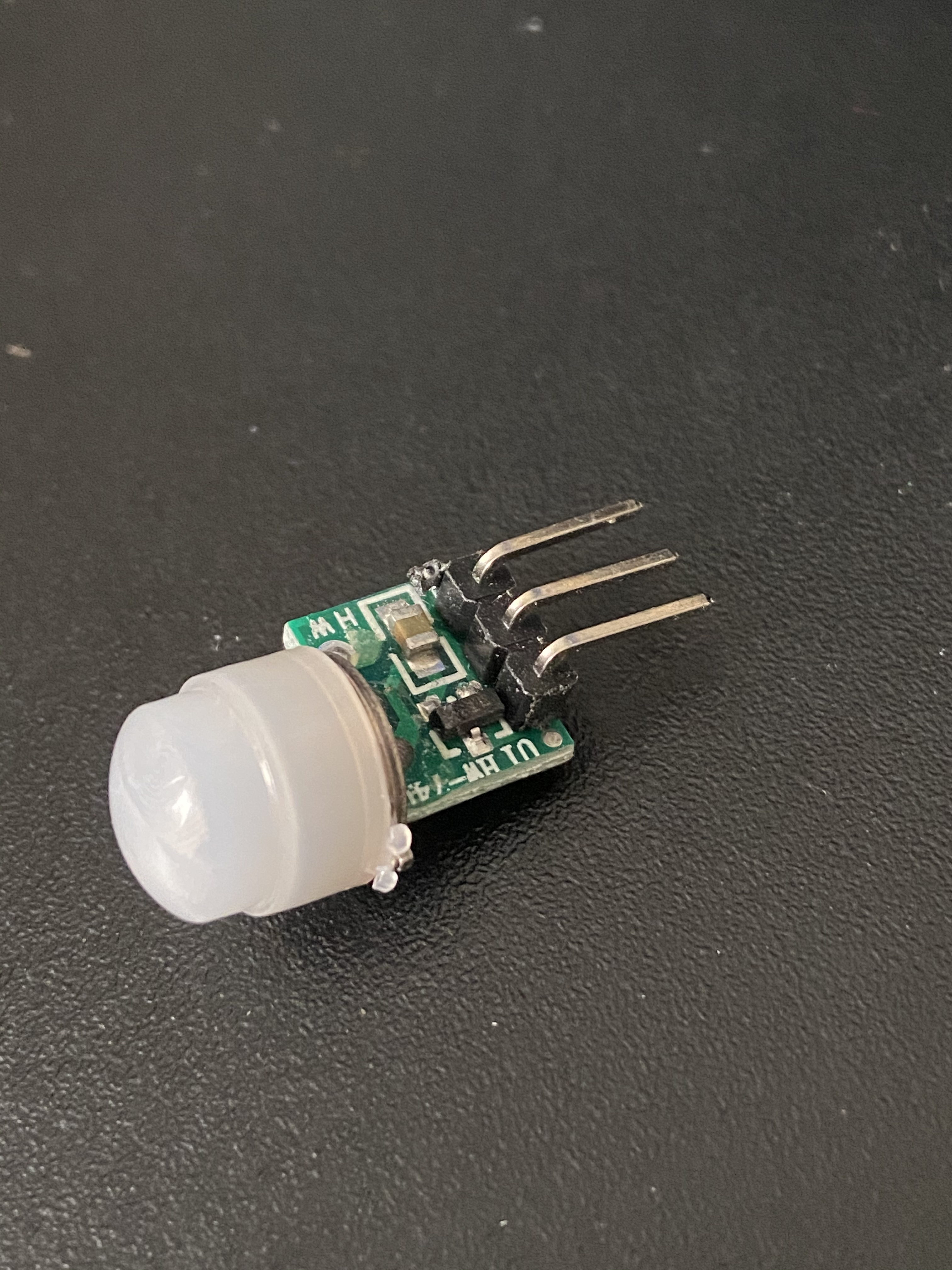
IR Movement Sensor
An IR movement sensor contains their a chip in order to tell them how to behave. Depending on the brand and size of the sensor this chip may be incased within the sensor or connected to it. You will notice three leads coming out of the bottom of your sensor. The outside ones connect to power and ground, while the middle pin will output either a high or low signal depending on if the sensor is triggered.
All objects give off a trace amount of infrared radiation that is invisible to the human eye, and these sensors can detect that radiation (often interpreted as heat) within their field of vision. The sensor will take a snapshot of the amount of radiation it can detect and compare it to the previous one. if it detects a large enough difference, the middle pin transmits a HIGH signal. Otherwise it transmits a LOW signal.
So we have gone over a lot of information in just a few short pager so lets take second to review before going onto the chapter assignment: Controlling multiple LEDs with a single input.