Connecting Arduino to P5
We are in the home stretch now. We have built a circuit that measures input from a voltage divider and sends that information out via a USB connection. All we have to do now is tell P5 where to find this data and what to do with it. But first, there is one more starting template/library that we need.
P5.serial files
This is a library made by the authors of this course, and is designed to work together with the arduino code from the last chapter (we will go through both of the sketches in more detail here)
You can access the starting template of the P5 sketch below. (also in a link in the following paragraphs)
Make sure that you have all of the necessary external libraries included in your HTML file like shown below.
<!DOCTYPE html>
<html lang="en">
  <head>
    <script src="https://cdnjs.cloudflare.com/ajax/libs/p5.js/1.2.0/p5.js"></script>
    <script src="https://cdnjs.cloudflare.com/ajax/libs/tone/14.8.9/Tone.js" integrity="sha512-nUjml8mN4CNYqBAy0ndDrd8pJV/eTtBNDsnvNtPqozx9/BccUeWSoKW14qWkQUnhuh8E3m+yra3qdzM68lqPEQ==" crossorigin="anonymous"></script>
<script src="https://cdn.jsdelivr.net/gh/molleindustria/p5.play/lib/p5.play.js"></script>
 <script src="https://cdn.jsdelivr.net/gh/vanevery/p5.serialport/lib/p5.serialport.js"></script>
    <script src="./PDMSerial.js">
   </script>

    <link rel="stylesheet" type="text/css" href="style.css">
    <meta charset="utf-8" />

  </head>
  <body>
    <script src="sketch.js"></script>
  </body>
</html>
You can simply open a new project, go the index.html file, and replace its contents with this code. This will be useful for the remainder of the course since it also has p5.play and tone.js included as well.
We also need a few extra files top be added to our file browser in order for this to work properly. These have all be collected in this template file which you should duplicate to your account to use as a starting place for this unit. These files are javascript libraries made by one of the authors of this course. We don’t need to go into the details of these libraries, but know that they take a lot of the complicated web-development aspects that this course does not cover and simplifies it into an easy-to-use format that will allow us to transmit data between the two platforms easily.
Practice Time!
You can explore these codes if you want, but be sure not to change anything. That could break the project entirely.
Once this library is installed, we will be able to utilize serial communications in P5, as well as the p5.serialcontrol app that was mentioned at the beginning of this chapter. Remember that these lessons will not work without the app and libraries.
Coding in P5
Now let’s look at the code from the template I just gave you. There are a few things we need to go over before going back to Arduino.
The first is the line let portName = '/dev/tty.usbmodem1452401';. In order for this to work we will need to give our code the ID for whichever usb port we need to communicate with. We will go over that later, but it is extremely important as each usb port has a unique number assigned to it.
Sending Data
In this code you will notice a few lines that begin with serialPDM.transmit. This is the command to transmit some data through the USB cable to the Arduino. We can transmit any value we want when this is called. All you need is a label for the data, and the actual value itself. We can see in this sketch that that can be a hard-coded number or something stored in a variable.
Receiving Data
This process happens a little more automatically with this setup. In the next step we will go back to Arduino and set up the board to send messages. Like in P5 however, these messages need to have a label (as a string) and a value. We can see in the code comments what labels we are looking for in this sketch. These can be changed depending on what you are doing, but for this lesson we will keep the same ones.
- .a0 will be the voltage coming in from the analog input 0.
- .float0 is the same pin, but mapped to a range of 0.0-1.0.
- .pressure will be the value coming in from analog input 1. This will have a sensor of some kind attached.
- .p7 is the value of digital pin 7.
We can use these values by calling sensors.a0, or sensors.p7 like a variable in our code. (see the draw() function for an example of this)
Practice Time!
Continue ot explore this sketch if you want, but know that if you run it you will get very erratic behavior, undefined values, and possibly several errors all at once. We need to go back into Arduino one more time before everything works properly.
Back to Arduino
This chapter has a fair bit of switching back and forth, but this is the last big switch… for now.
We need to go back into Arduino and tell it to send the messages to P5 so that we can utilize the various sensors that we just listed. Like with the P5 sketch, the authors have created a starting template that includes all of the necessary files and libraries. You can access that file here or in the previous lesson. If you are utilizing the downloaded application instead of the web-editor, simply click on the button with three dots, and select download sketch. This will download everything you need into one folder. (be sure to keep all of the files in the same folder)
You will notice a lot of the same things we saw in the P5 sketch are present here. We are setting specific pins based on how we want to utilize them. This isn’t anything new at this point, so lets move on down to the loop.
Inside of loop(), we begin with the normal aspects of checking a pin value and storing it within a variable. Next is where the new things begin to appear. We can see pdm.transmitSensor() called several times. In this section is where you can give data a label (as a string) and transmit it to P5. Just like in P5 each piece of data needs a label, and in order for this to work properly you MUST have the labels batch between P5 and Arduino. Otherwise the computer will be unable to use the data properly.
For this example, let’s wire in a pressure sensor (or whichever sensor you have access to) and connect it to pin A1. Refer back to the lesson on sensors if you need a refresher on how to do this. You don’t need to connect the other sensors and elements mentioned in th code for now. We will send this data to P5 shortly.
Tip
If you do find yourself in an instance where the labels do not match up, it is slightly easier to change the label in P5 since you don’t have to re-upload the sketch to the board.
Lastly when transmitting data, notice the line pdm.transmitSensor("end");. This line tells P5 that the Arduino has finished sending the data for this loop. You MUST put all of the data values you want to transmit before this line in the loop. The other order doesn’t really matter, but any values transmitted after this will not be read by P5.
Receiving Data in Arduino
The final section of this code is a conditional:
if(newData) {
    if(pdm.getName().equals(String("led"))) {
      digitalWrite(outPin, pdm.getValue());
    } else if (pdm.getName().equals(String("fade"))) {
      analogWrite(outPWMPin, pdm.getValue());
    }
  }
This conditional will check to see if any data is being transmitted from P5 (see earlier in this lesson). Then, the inner-level test will sort this new data based on the label we gave it in P5 (again, the names MUST be a perfect match), and then uses that data to affect something on the board. In this case, the board will receive instruction to turn one light on, and control the brightness of another.
P5serialControl
This is the final step in coding for this course. Take a moment to pause and see how far you’ve come over the past several units.
The last thing we need to do is setup the USB port properly. A USB port behaves similarly to a virtual parking space. If you park a car in a space you can utilize all of the things available at that space, however you cannot park in a space that is already occupied by another car because there is no room. A USB hub acts like a parking garage, where the garage has a single address, but each space will have a unique number assigned to it. If possible, I recommend plugging the Arduino directly into the same port directly into the computer for the remainder of the course.
A USB port is the same way. Different programs can connect to the port, however only one can utilize the connection at a time. This can become problematic because we need Arduino to write the code to our board, but also P5 to receive and transmit data with the same connection. This is where the serial control application mentioned at the beginning of this chapter comes into play.
If you have not already, look at this page for instruction on how to download this program. Once you have, we can move onto the next step.
Be sure to flash the template code we were just looking at to your Arduino. Once this is complete go to tools and select “check port”. This will tell you which port to look for in the next step. Then close the Arduino application. If you are using the web-editor, you must pause the create agent that was needed to run the connection through the browser. Once that has been done, you can open the serial control application.
This is a simple application that helps to manage the USB connections in P5. What you need to do is select the USB port with the arduino connected to it. This may be confusing if you have multiple things connected to your computer, but if not, then the list should be fairly short. On Windows devices the name will be something along the lines of COM3 or COM5. on Apple computers, it is a little longer and looks like /dev/tty.usbmodem1452401. Once you have found the correct port, select the “open” button in the serial control app. This will create a connection that will let P5 connect to the Arduino board and keep any other programs from interrupting the connection. Next, copy the port name exactly as it appears in the serial control app and head to the P5 sketch. You don’t need to worry about the other parts of the serial control app. The libraries we installed in P5 and Arduino are handling everything else we need in the background.
In the starting template, find the line let portName = '/dev/tty.usbmodem1452401'; and replace the contents of the string with the new name you just copied. At this point, we have now completed everything needed for the codes to talk to each other.
Talking Codes
At this point, you should notice a few thing happening when you run the code. There will be several instances of “undefined” popping up on the screen, and possibly an erratic purple circle appearing and disappearing. This is OK. Try pressing on the pressure sensor. You should notice the number on the screen increase and decrease. Remember, the Arduino is measuring the changes in voltages, mapping them, and then transmitting the number along with a label to P5 via the serial port. P5 is simply routing the data based on that label to whatever we need it to do. Try changing the pressure sensor from A1 to A0 on the breadboard. You should now notice that instead of changing the numbers, the x-position of the circle changes as you adjust your pressure. Next, lets work on adding the final elements needed for everything included with this template.
Final Practice
While we have made the codes be able to talk to each other, there are a few things we will need to do in order for things to work out properly. Mainly, we need to set up the breadboard to have all of the elements Arduino and P5 are expecting. You can utilize the sketch as a starting point, or create your own sensor setup.
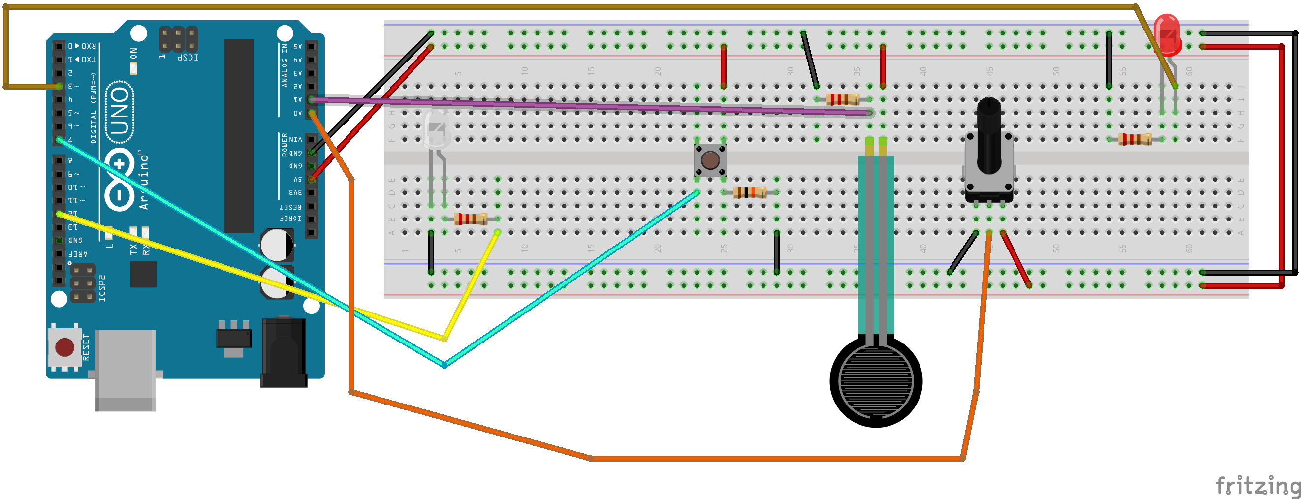
Once this is set up you will notice the following code behavior:
- P5 will display some values as text on the screen. These will respond to various sensors and buttons in real-time.
- A purple circle will appear on the computer screen in P5. The size of the circle will change depending on a sensor value.
- One LED will turn on and off when a button is pressed on the keyboard.
- Another LED will change brightness when the mouse is clicked and dragged across the P5 canvas.
Once you have gotten this working, experiment with various other sensors and values you can transmit. The final project will be to combine everything into a single sketch that can communicate with an Arduino.