Chapter 11 Review
Lets go over some of the basics from the previous lessons:
Analog Signal
An analog signal is made up of multiple potential values within a given range. While we can view the range as a set of numbers, in actuality these values correspond to the amount of of electricity running through a specific point on the circuit. A value of 0 means that no electricity is passing through the circuit, whereas a value of 1023 (on the Arduino Uno) indicates that at least the maximum amount of measurable electricity if flowing. Different kinds of circuit boards and sensors may allow for larger (or sometimes smaller) ranges with more specific values, but these ranges can be scaled and mapped to fit whatever parameters we need within the coding portion of our projects.
Remember, digital signal only has two possible states: HIGH and LOW, whereas analog signal can have a wide range of potential values.
Voltage Dividers and Variable Resistors
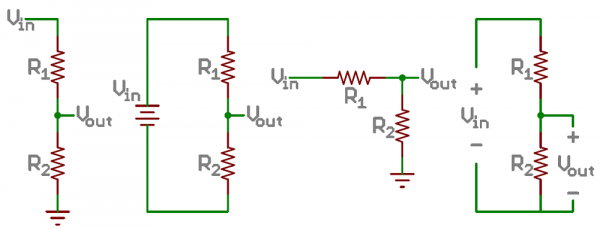
In order to generate the analog signal that we can read with our Arduino’s analog input pins, we need to have something that can manipulate the amount of electricity flowing through the circuit. A voltage divider is comprised of two different resistors. And by changing the amount of resistance in one, the amount of change in electricity between them can be measured. Below is a diagram of several different ways to set up a voltage divider:
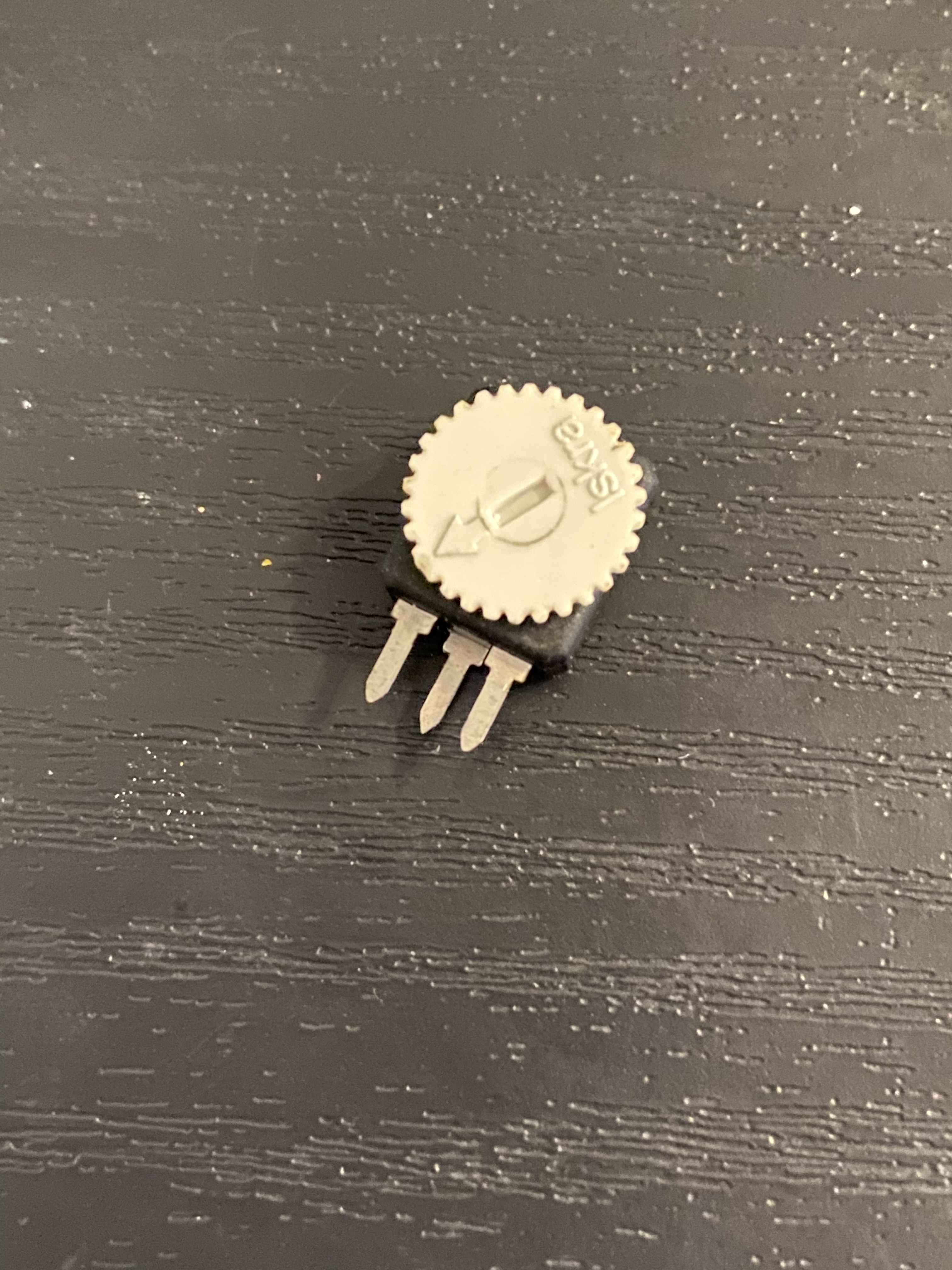
Many of our sensors are contained voltage dividers. While not a hard rule, these components can generally be identified by their three leads that we can connect to a breadboard. Generally, the outer leads serve as the voltage in and ground in the diagram above, and the middle lead is the voltage out. When we connect a potentiometer to a circuit, it is the middle pin that we are measuring with the Arduino’s input.
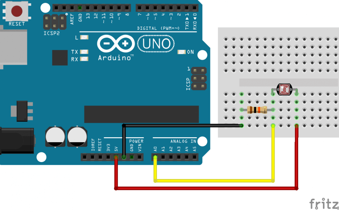
Other sensors, such as photo resistors, only make contain a single resistor. These resistors can change their amount of resistance through different means. A photoresistor will respond to light, a flex sensor will respond to being bent, etc. In order to use them, we need to include another resistor somewhere with in the circuit. Essentially we are creating our own voltage divider instead of using a pre-made one when we do this.
Pulse Width Modulation
We can use analog sensors and outputs in order to create a gradual change in signal strength of digital components. This is commonly done with LEDs. It may not look like it, but even though we can use PWM to have and LED fade in and out, it still only has two main states: ON and OFF. PWM happens when we change the ratio between these two states over time. The amount of time that the LED is on is called the duty cycle. This idea is shown a little more clearly in the diagram below.
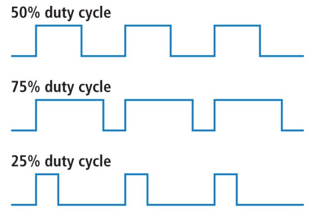
Because the signal is transitioning between on and off faster than the eye can see (This is happening approximately 100 times per second in LEDs), humans will interpret what as happening as a change in brightness of the light. Compared to being on 100% of the time, a LED being operated with a 25% duty cycle will only be in the ON state for 25% of the time, so it will appear 25% as bright by comparison.
Chapter 11 Review Assignment
The upcoming assignment is to create multiple dimmer switches for multiple LEDS using PWM AND different analog sensors . In order to practice for that assignment, start with the Arduino code from the PWM lesson. only this time experiment with different sensors and variable resistors in order to see which ones you like working with, or which ones are problematic to get the results you want.