LEDs in a circuit
The Circuit components
in the previous section we created and uploaded the code to our Arduino that will control our new LED. The next step is to build our circuit. First we will need the following components:
- the breadboard
- jumper cables (red, black, and a different color if possible)
- led (of any color)
- 270 Ohm resistor
270 Ohm Resistor
This will most likely be the most common size resistor that you utilize within this course as they work with the Arduino’s power supply and the LEDs. You can identify them using this chart:
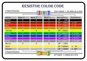
Depending on the number of bands on your resistor, you must interpret this chart slightly differently. A 270 Ohm, 5-band resistor will read red, violet, black, black, brown.
- The first 3 bands tell you the hundreds, tens, and ones digit values of the resistor, teh 4th band tells you what to multiply the 3 digit number you just received by, and the 5th band gives a range of variance that can occur with that resistor. This final band is almost always brown or gold, and will help you read the resistor in the correct order.
Breadboard
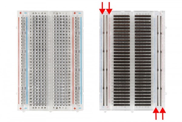
The breadboard is what we will use in order to build our circuits. it is comprised of multiple holes, and electrical current flows in a specific pattern through the board.
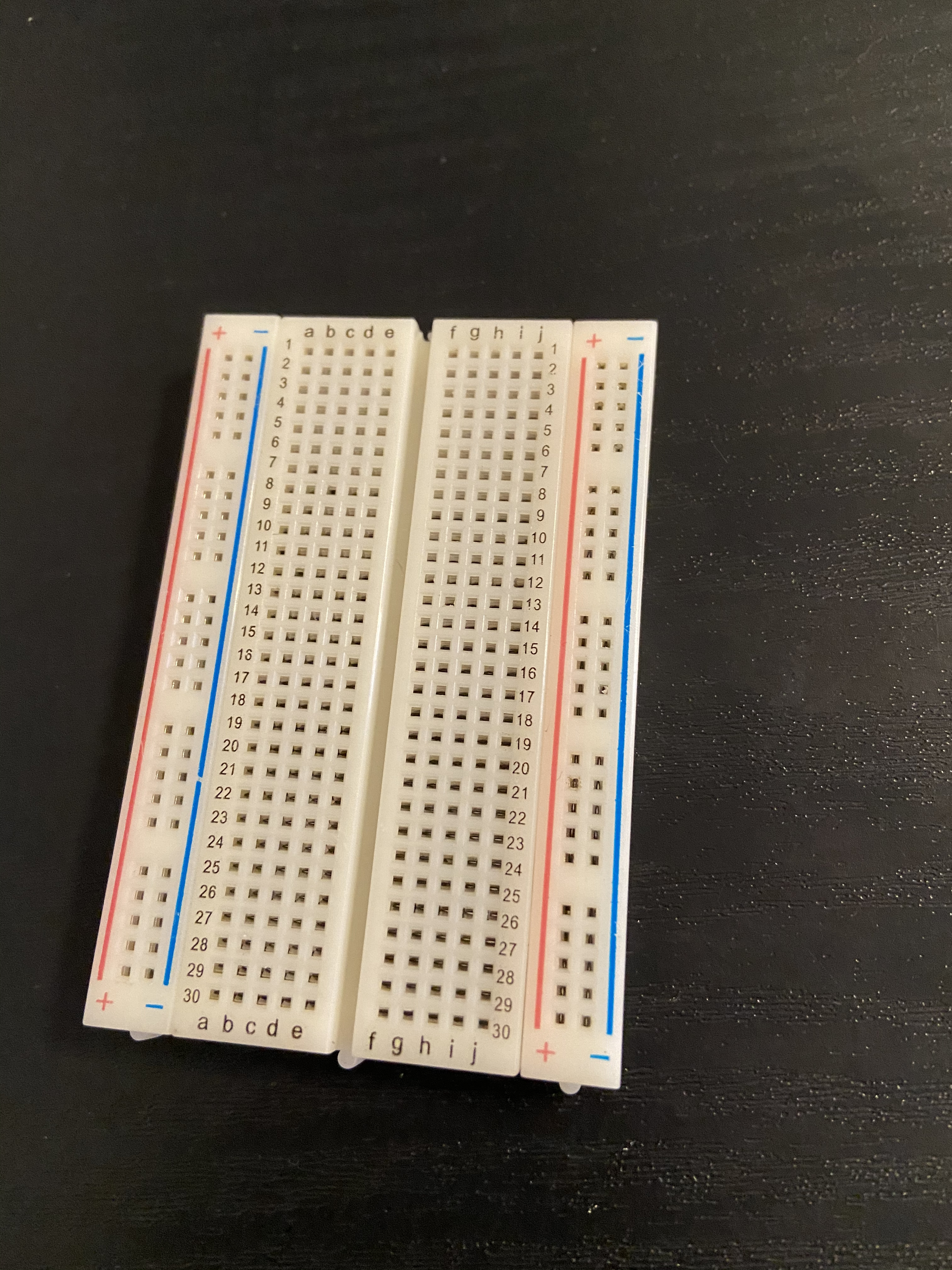
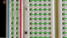
Looking closer at the holes, we can see a mirrored pattern. On the outside edges are two vertical columns labelled + and -, and in the middle ate two series of rows labelled with numbers. The current flows vertically along + and -, connecting everything in that column, and horizontally through each row so that everything in row 5 (for example) is connected. the connections do not cross the divide in the middle of the board.
We can connect the ends of our jumper cables and component lead into this board in order to connect them without solder. This is a great tool for making changes to a circuit when you are still prototyping.
Building The Circuit
Now we will finally get to building the circuit.
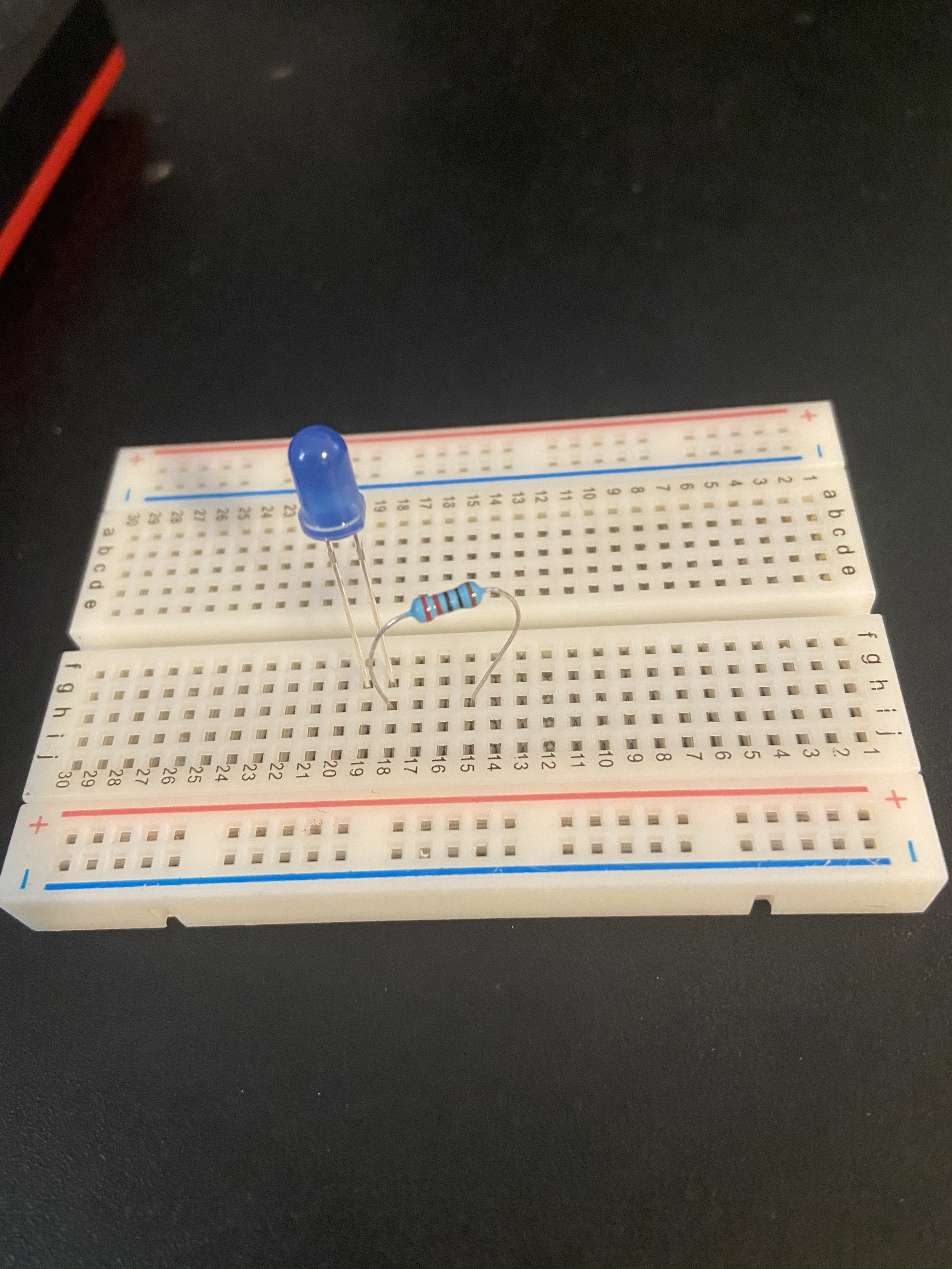
First place the LED into the breadboard between any 2 different numbered rows. you may have to apply a little force if your breadboard is new. Just be patient and try different locations. Then connect one end of the resistor to the same row as the short lead of the LED, and the other to an unused column. Bending the leads is ok.
Next take your colored cable and connect it from the second lead of the resistor to the - column
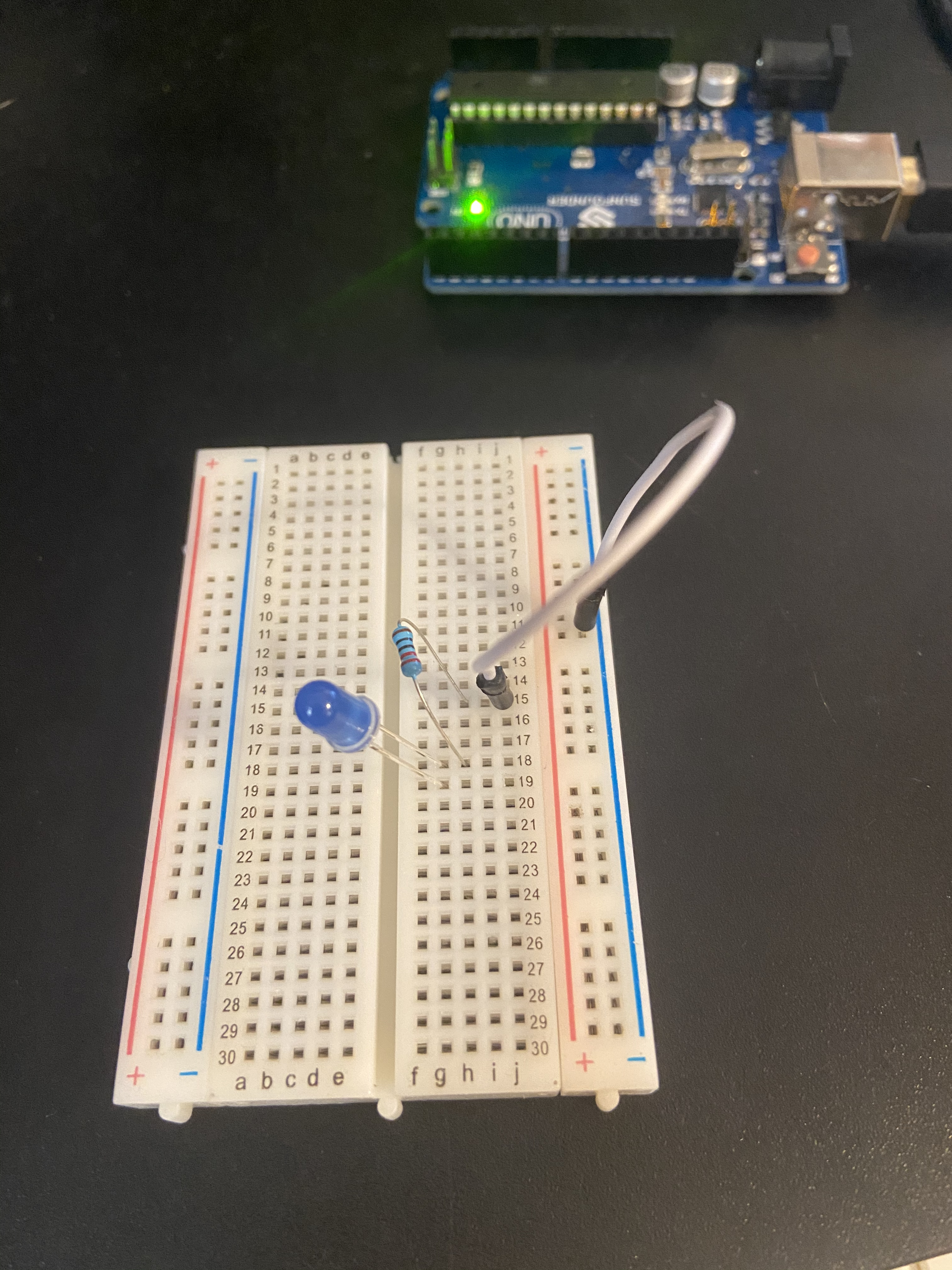
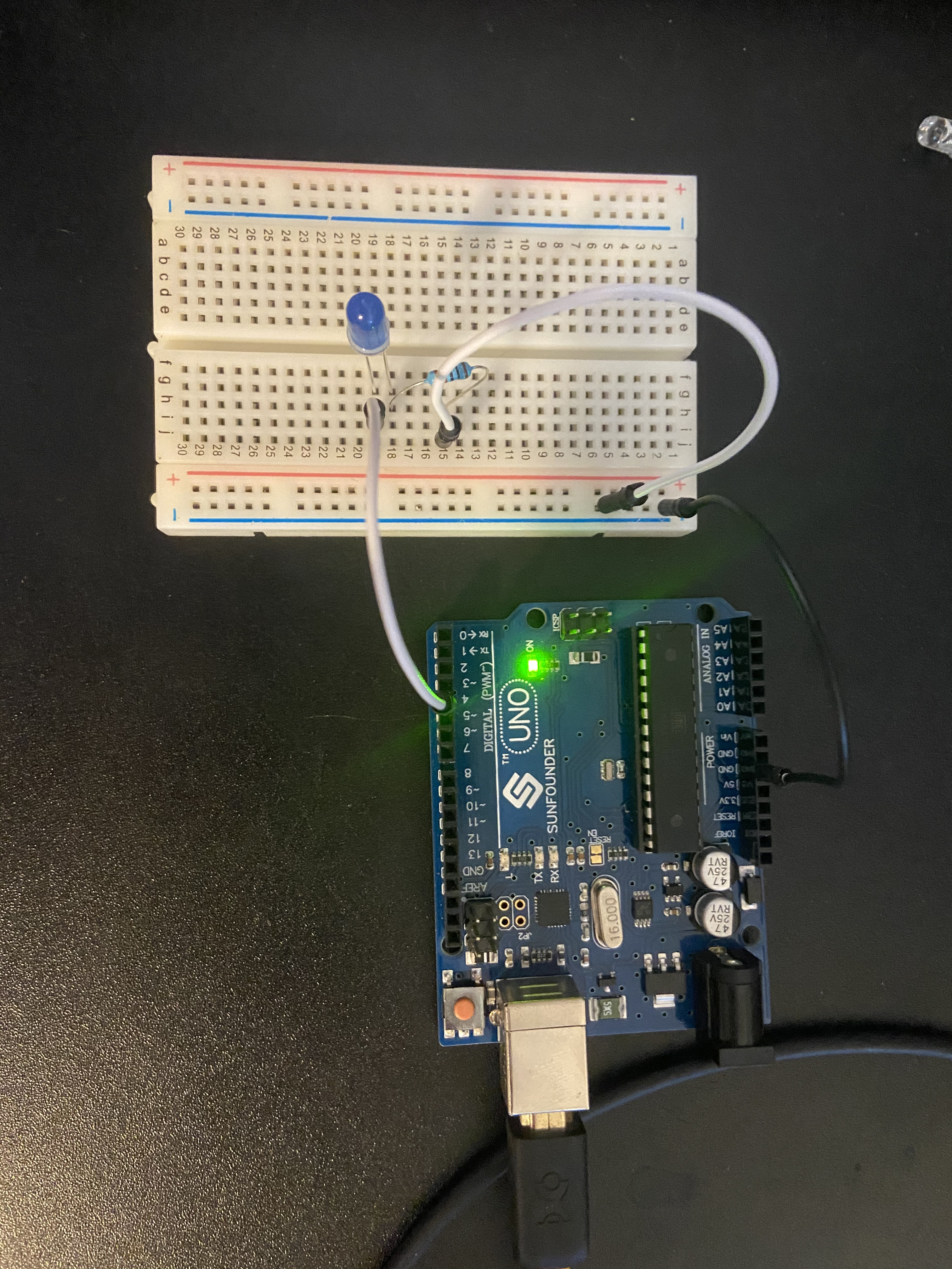
The second to last step is where you will connect the breadboard to your arduino. Use the black cable to connect the - column to the pin connector labeled ‘gnd’ on the arduino, and use the red cable to connect the ‘5v’ pin connector to the same row that the long lead of the LED is connected to. You should see the LED turn on and remain on. (Keep in mind that you will have to keep the arduino connected to a power source through either the USB connection or a 5V power adapter in order for the code to function and electricity to flow through the circuit)
Here is a diagram showing the circuit from the top-down. More information on diagrams will be presented later in the lesson.
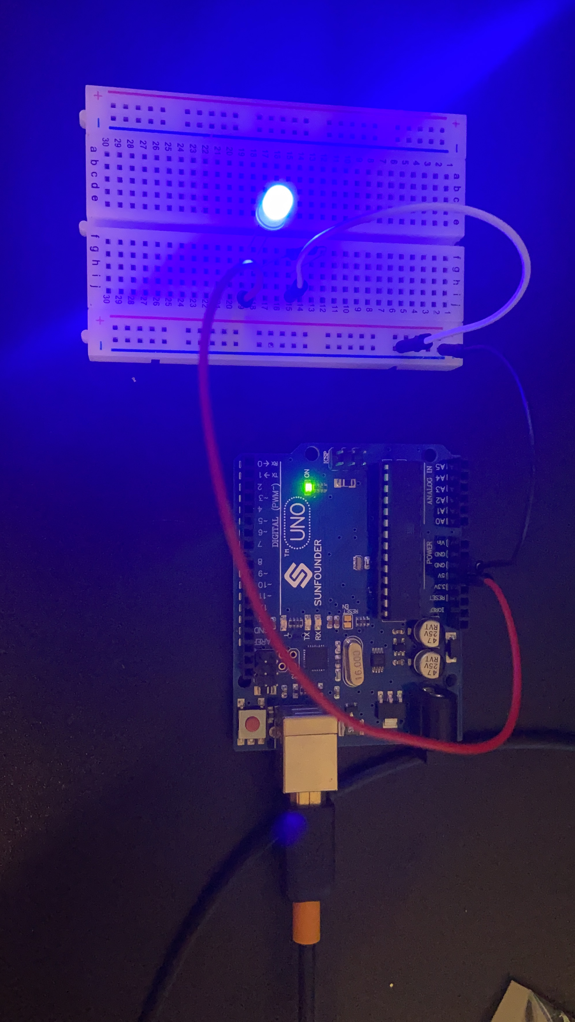
This is almost what we want, but lets take a second to look at what we have. We are sending 5 volts of electricity from the Arduino to the led via the red cable (positive is always red if possible), that current is flowing through the LED, to the resistor, to ground (-. ground is usually black or white cables if possible) All of the connections are made by the breadboard. The 5V however is constant. You can see the built-in LED is still flashing. Simply change the red cable so that it connects to pin 4 (or whichever pin you specified in the code) on the Arduino instead of ‘5V’.

Congratulations! you have made your first circuit with Arduino!!
Circuit Diagrams
Now that we have made a circuit, lets talk about different ways we can utilize a graphic representation of the circuit.
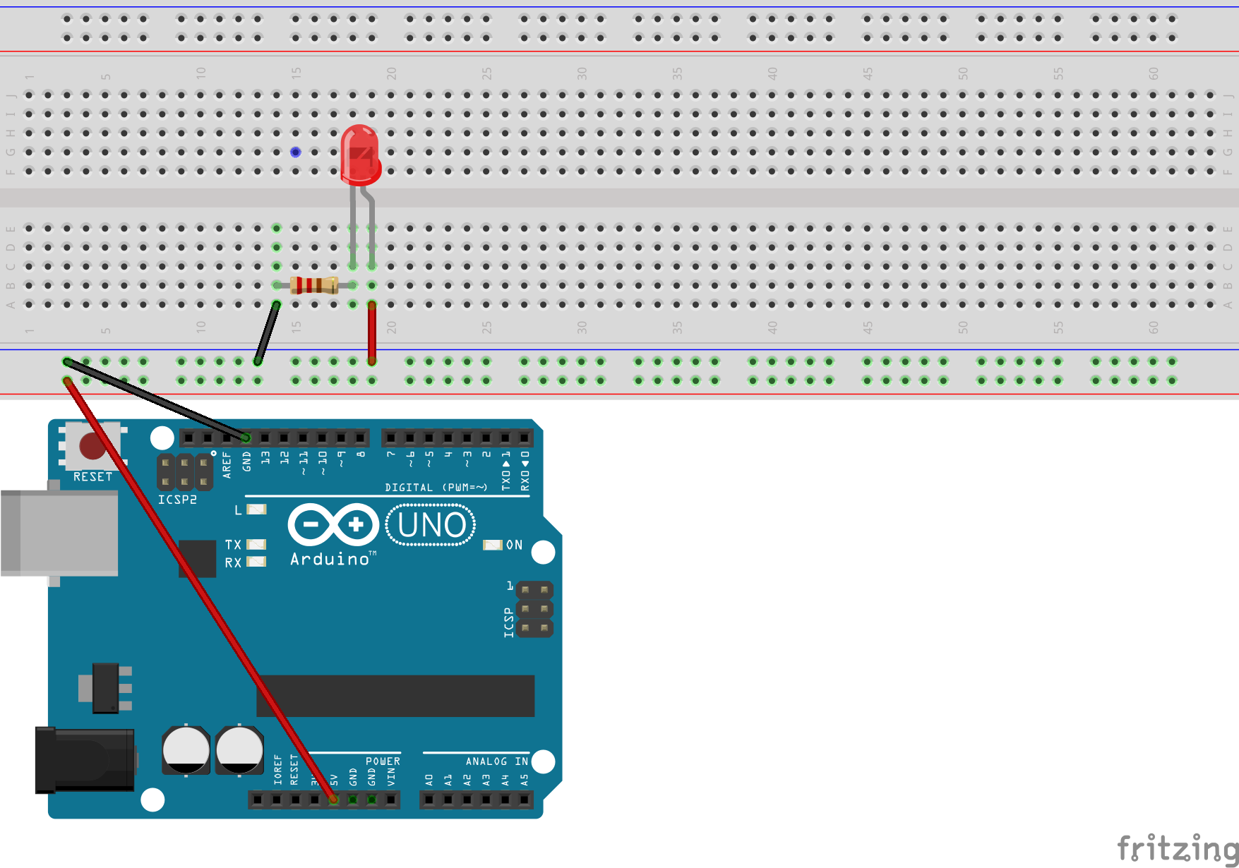
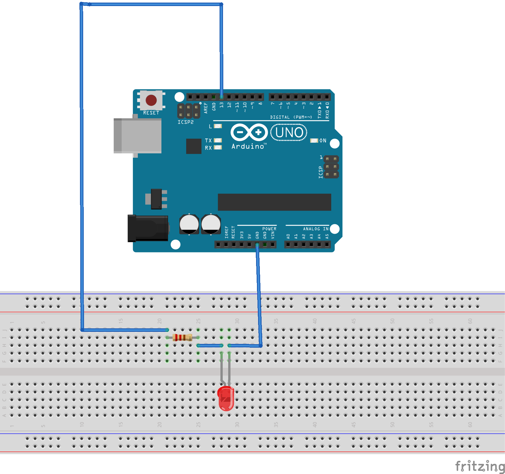
The first way is with images showing exactly which parts need to connect on the breadboard. These are helpful, but limited to a specific instance or set-up. These diagrams are usually used as part of a help file or tutorial. The image below is a version of the circuit we just built, but utilizing pin number 13 instead of number 4.
Another way is a little more traditional, and only shows what elements need to be connected together. This diagram allows for a little more flexibility in where you can place things on the breadboard. These can be used for everything previously mentioned, but are also used for describing existing circuits as well. This particular diagram represents a recommended circuit for the final project, however you will notice that unlike the breadboard diagrams, it only shows what elements are connected, not where they should go physically.
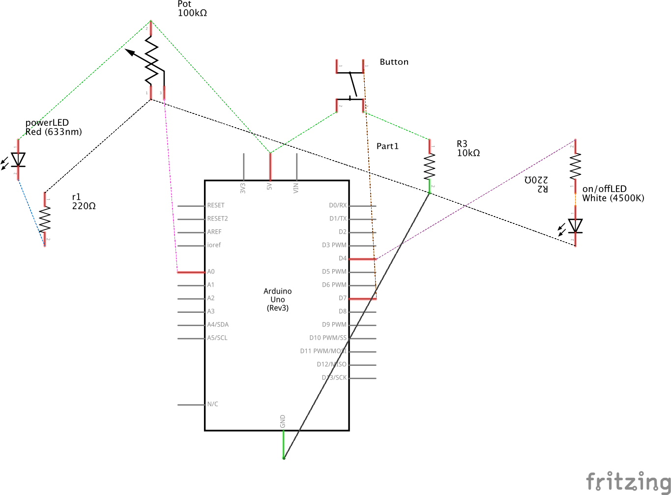
These types of diagrams contain fairly standard images to represent various components. The link below will show what some of those are and how to interpret them in a diagram.
Here is a link to some slides that show some of the different kinds of circuit diagrams.